Eng-Tips is the largest engineering community on the Internet

Intelligent Work Forums for Engineering Professionals

Double 3-Sided Roof Diaphragm 5

StrEng007

Structural
Aug 22, 2014
486
0
0
US
I have a building that features s pop up roof section. Please see the image below.

Screenshot_2024-10-07_152347_jihc18.png


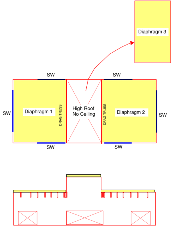
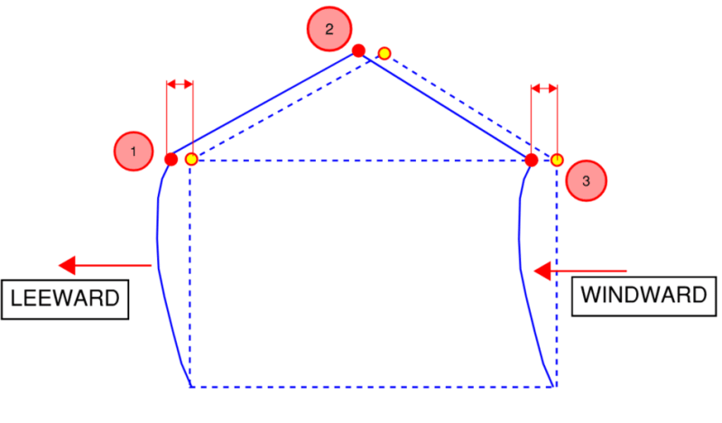
Long story short, I have a hole right in the middle of my roof diaphragm. Based on the shear wall layout, there is no vertical element to support the edges of the roof diaphragm shown as #1 and #2.
Would this be a candidate for each diaphragm to be treated as an "open front diaphragm"?

In all the design examples I've seen, the open front end of the diaphragm didn't have an additional "point load" in the transverse direction.

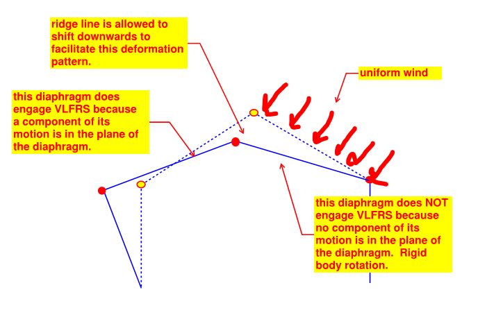
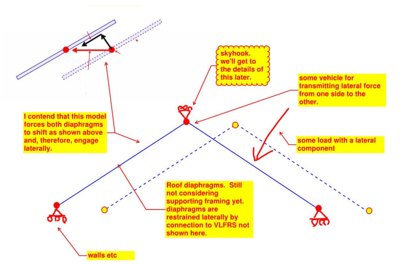
Additionally, what I'm not showing is the fact this roof is a gable. I've shown it as being flat because that helps me first get an understanding of the approach I want to take. My second concern here is being able to get a 3 sided diaphragm to work as a gable roof with a steep slope.
 
Replies continue below

Recommended for you

For starters, how different is my typical approach from what you suggest? I'm referring to the two examples I showed above. I think we need to first determine how the wind applied to the roof is handled (i.e. projected vertical area). Wind loads from the 1/2 wall height is straight forward.

After that, it's a matter of how the loads enter and travel through the diaphragm.

I'm assuming this path we're headed down is going to discredit the ceiling as a diaphragm? Especially since that is really a shortcut to alleviating all of these questions.
 
I would like to lead the discussion for the first bit StrEng007. I expect to be able to answer all of your questions during the course of that. If I don't, the floor is yours.

StrEng007 said:
I'm assuming this path we're headed down is going to discredit the ceiling as a diaphragm?

It won't rely on the ceiling as a diaphragm in homage to how things are done where you and I practice.
 
Let's start with some fundamentals.

1) Diaphragms are only engaged structurally if they are induced to move in their own planes. Rigid body diaphragm rotation and diaphragm translation perpendicular to the diaphragm do not engage diaphragms structurally. I take this as self evident.

2) A sloped diaphragm that is shifted laterally in space is induced to move in its own plane because the lateral motion contains a component of motion along the plane of the diaphragm. Therefore lateral motion engages a sloped diaphragm structurally. See my sketch below. This probably should be obvious but I struggled with it for a long time.

We good on these points? I have more than one way to present this if more is required. I love vectors as much as the next guy but they tend not to be super effective at changing hearts and minds.

c01_vejzbe.jpg
 
StrEng007 said:
What I've attempted to understand here is HOW we assume these two planes act together. What really trips me up is that I think the proper way to handle the 1/2 projected wall height is to take the lateral load coming from the wall, and find the vector that pushes load into the plane of the diaphragm.

I agree completely and have shown a situation below where I believe that the left diaphragm does not, in fact, participate in resisting load. If we're on the same page with this, I'll get into what is required to encourage both diaphragms to participate as we typically do in design.

c01_enfcko.jpg
 
KootK said:
have shown a situation
I realize that a situation means "just one scenario" and that you aren't referring to all scenarios.

In order for me to move forward, I have to acknowledge a couple of things, and understand that your scenario is intentionally not considering these items.

Do we agree that your model is intentionally NOT looking at:
1. That applied wind or seismic will have forces on each side of the building (i.e. windward/leeward wind).
2. That overall drift of the building (not diaphragm) will move nodes 1 and 3 to the left.
3. That we likely assume there to be some local deflection in the vertical wall elements (not sure this one matters at all for your situation).

Screenshot_2024-10-11_161232_ly3cax.png


If all of the above is intentionally put aside, I have some questions that remain on the theory:

1. We're only looking at rafters, right? Similar to if a collar tie was present, a real truss is going to complicate this?
2. For the left side diaphragm, it's equivalent to sheathing wall and just tilting it up. But we know this is restrained at its ends (shear walls) that will prevent it from being infinitely tilted over. Doesn't the fact that it's restrained at the end boundary influence some diaphragm action?
 
strEng007 said:
1. That applied wind or seismic will have forces on each side of the building.(i.e. windward/leeward wind).

Yes. More complex situations can be handled by way of superposition. It is just easier to elucidate important points by paring the situation down to only that which is truly necessary.

strEng007 said:
2. That overall drift of the building (not diaphragm) will move nodes 1 and 3 to the left.

Yes. For the sake of discussing diaphragm participation, all that matters is relative displacement between the diaphragm and the VLFRS.

strEng007 said:
3. That we likely assume there to be some local deflection in the vertical wall elements (not sure this one matters at all for your situation).

Let's assume that there won't be. It's not germane to any of my arguments.

strEng007 said:
1. We're only looking at rafters, right? Similar to if a collar tie was present, a real truss is going to complicate this?

I'll get to this later. For now, I've deliberately limited the presentation to pin ended rigid bar models to keep things simple. Consider the model to not represent anything other than a pair of generic, weightless diaphragms.

OP said:
2. For the left side diaphragm, it's equivalent to sheathing wall and just tilting it up. But we know this is restrained at its ends (shear walls) that will prevent it from being infinitely tilted over. Doesn't the fact that it's restrained at the end boundary influence some diaphragm action?

No, I don't believe that it does. We're not talking about infinite tilt or even significant tilt. As with most things structural, we're limiting ourselves to small deflection theory.

c01_l9qqnu.jpg
 
KootK said:
It is just easier to elucidate important points by paring the situation down to only that which is truly necessary.
OK, I'm with you on all your other responses. I will have to set aside the leeward wall wind and let you continue on with the interaction theory.
 
Couldn't you run a continuous chord/collector through the top/bottom walls and then it's more conventional four sides and you need to create the necessary load paths? That elevation suggests there's no windows that interfere with a continuous chord on those elevations.

You need the drag truss to stabilize the pop-up roof against up-down wind.

I feel like this analysis is getting more esoteric than it needs to be.
 
lexpatrie said:
I feel like this analysis is getting more esoteric than it needs to be.

It's an attempt at an esoteric ansnwer to what is, fundamentally, an esoteric question. One that has been bothering OP for years and that no one other than me has thus far made any attempt to resolve.

StrEng007 said:
I return to this question every couple years and end up just accepting normal practice because it's become so time consuming. But there has to be an explanation that I'm not seeing.

I'm trying to help here lexpatrie. The best that I know how. If you think that you can do it better, have at it. The floor is yours.
 
Mirroring the popcorn eating post - I think this is worthwhile and I'm enjoying following along.

If nearly every system in a building structure is a spring, and springs that aren't stretched don't generate forces, then it's helpful to think through how the leeward diaphragm ain't-a-being-stretched-a, and there for doesn't generate any meaningful forces, and therefore is just going along for the ride, and therefore falls out of the analysis.

Please do continue on!
 
Well, the conclusion that I'll get to eventually is that, in most practical cases, it is reasonable to assume that the diaphragms share load. Probably not as uniformly as our methods suggest but whatever.

StrEng007 said:
Now for the wind that is normal to the roof (i.e. roof wind load), I understand there is no axial force in the plane of the roof due to wind (therefore you cannot say that wind is pushing parallel into the plane of the roof). But based on the vertical projection of the roof, there is a lateral reaction at the eave and ridge. You can solve that with a FBD, but I don't understand the mechanism behind how the diaphragm "feels" this shear load transfer in the plane of the roof since the wind component is normal to the roof.

So this is how I view that concern. Again, I'm not considering supporting framing yet. These are just skyhook diaphragms shifting around.

This follows the same logic as my previous investigation of the wall load case. Here, the left diaphragm receives the in plane wind load even though it is the right diaphragm that is acted on by the wind directly. And the question becomes, just as you have postulated, why does the right diaphragm "fee the shear load". I'll start speaking to that next.

c01_xzxwsx.jpg
 
In the sketch below, I've created a model that I believe would force both diaphragms to engage laterally for all of the load cases that we've considered so far. The skyhook restrains the diaphragms from rigid body rotation that would produce no in plane diaphragm shear and forces both diaphragms to shift laterally.

I've made this deliberately abstract to drive home the point that I'm trying to make. We'll get into the practical details of the boundary conditions next.

For now, are we agreed that if the boundary conditions shown below were present, both diaphragms would engage?

c01_i6glon.jpg
 
Back
Top