Eng-Tips is the largest engineering community on the Internet

Intelligent Work Forums for Engineering Professionals

dv/dt filters or sinus filters for motor with cable length of 60 meters/200 ft? 9

Status
Not open for further replies.

edison123

Electrical
Oct 23, 2002
4,409
0
0
IN
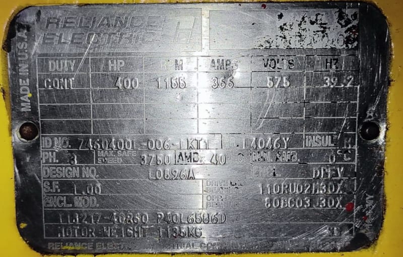
Cage motor is rated for 575 V, 366 A, 4 pole and runs at 25 to 40 Hz.

Siemens VFD model 6SE7238-6FS00-3AD0-Z has a front end filter on the input side and a RL90003 Reactor on the output side.

The motor cable length is 60 meters/200 ft and there have been many stator winding failures due to turn shorts leading to ground fault. All the original and rewinds are with VFD duty rated class 180 deg C magnet wire and class 200 deg C rated aramid paper ground insulation.

Are dv/dt filters or sinus filters at the VFD output needed to prevent the stator winding failures with the 60 meters/200 ft motor cable?

Muthu
 
Replies continue below

Recommended for you

Parchie

Thanks. That's an excellent point about electrical resonance. We did test at 50 Hz only in our shop. This is a worthwhile experiment doing at client's site. Do you expect the vibration alone to change or expect to see voltage spikes at the motor terminals, in which case, I need to hook up a power analyzer to record the waveform.

Muthu
 
Hello Muthu

I'm in Canada and see many 575V applications. Your motor winding pictures that shows the motor frame - the motor frame look like a water cooled unit.
I have had a number of customers using Siemens 575V VFD's that have killed motors- factory and EASA repaired units.

Your client needs to measure the input voltage into the VFD's. We call 575V power - 600 volt systems because the input voltages is aways higher than 575V.
Typically see 620 ~ 630 volts going into the 575V VFD. Due to the high buss voltages caused by the high input voltage, the VFD's will spike the motor winding
with extremely high voltage (I have seen / measured up to 2200 - 2400V at the motor terminals) The first turn and last turn in winding are subject to these
high voltages.
If your rewinding the motor, install silicone tubing over the first and last turn in winding (6-8 inches long)

If voltage is OK, then your may bee seen capacitance being built up in 60 meters cabling. If on vessel, possible not shielded.
Have client install quality DVDT filter on output of the VFD.

Mac
 
Hi Mac

Thanks for sharing your real world similar pita jobs. These motors are force cooled via a blower mounted on one end and it basically blows moist salty air over the windings once through. And rains in seas don't help. Ideally, they should have gone for totally enclosed motors but I guess space is at a premium in these oil rigs.

They do produce their own power with 600 V, 60 Hz DG. So, you have a good point about input to VFD being high.

Your tip to add silicone tube to the end turns is excellent. I will add that to our protocol. (Wish ET will let me give you two stars). One client is already talking to some dv/dt filter suppliers. Fingers crossed.

What beats me is that we have been rewinding many VFD driven motors for other clients with same technology and they have all been working fine for many years now with zero failures. So I am zeroing in on long leads being the problem in this case. Also, the resonance as smartly pointed out by Parchie.


Muthu
 
Looking at the manual for that drive (and now needing some pain killers for the headache it gave me), it looks as though the default "pulse frequency" (their term) is 10kHz for high dynamic response applications, such as where you have multiple motors on an application. 10kHz is definitely in a range where lead length can exacerbate standing wave pulse problems. You might not want to change that pulse frequency though because it may affect the performance, so I would be leaning more toward the dV/dt filter.

That said, you ALREADY have an output reactor in there, which would be PART OF a dV/dt filter, so you don't want two reactors in series because it starts to cause a voltage drop. Also, most dV/dt filters are designed for up to 4kHz pulse frequency, so they need to confirm what the drives are set for and consult with the filter supplier to see if they need to de-rate it if the drive must use the 10kZ level.


" We are all here on earth to help others; what on earth the others are here for I don't know." -- W. H. Auden
 

Yes. I know.
If for example the slots = 72 then the volt/coil is almost 100V which is excessive. In addition, the impact of VFD will only make the situation worse.
I am aware that it is more difficult to make that winding with 2 circuits because of too many wires in hand, but it is a more reliable variant, regardless of the fact that the genuine winding has 4 circuits.
In general, I avoid the case where the number of circuits is equal to the number of poles.
Regards
 
@muthu,
I would like to discuss something I found with the choice of line reactors as you have posted. I found out that the RL 90003 reactor is for 900A at 3%. But your application FLA is only 366A. As we all know, the reactor effectiveness depends on whether the inductance provides enough smoothing effect on the rather peak-ish pulse output of the VFD. The indicative parameter would then be the %Z of the reactor. Using the data from RL-900003, the inductance was found to be 0.04mH. With an FLA of 366A, the %Z is 1.53% (575 V line-line output).
Could this be the reason why the reactor failed to arrest the rough voltage wave to the detriment of the motor connected to the VFD? Please consider replacing the reactor with a true 3%Z (RL-40003 with 0.105 mH,400A or RL-50003 with 0.085mH, 500A). My calcs tell me the motor needed 0.0726mH to provide a 3% drop at the 366A current.
 
zlatkodo - Almost all the LV motors of higher HP have as many parallel circuits as possible. I understand each parallel circuit sees the full voltage thereby increasing the no. of voltage stress points. Is there any other reason why you avoid number of circuits is equal to the number of poles? In this particular case, I am planning to convert to single circuit to reduce the voltage stress point to one (which means I would have buncha conductors in hand, which is a major pita).

Parchie - Thanks for going through the reactor manual. I raised this point with our client just now and he said the reactor serves two motors. This is a VFD with one input and two outputs driving two motors in tandem. In that case, the reactor rating of 900 A is reasonable? This raises another question. Will one reactor for two motors work as intended or is it better to have one 450 A reactor for each output?

I have asked the client for more data on the VFD, reactor setup etc. Will post them once I have them.

Thanks again to all of you for spending valuable time on this.

Muthu
 
Hi, edison,
edison123 said:
In this particular case, I am planning to convert to single circuit to reduce the voltage stress point to one
I think it is good idea.
edison123 said:
Is there any other reason why you avoid number of circuits is equal to the number of poles?
Yes. If the number of circuits is equal to the number of poles, there is no more possibility of applying the most suitable connection (skip pole, adjacent pole), which is very important in some cases.
BTW, is it about 250 kW motor? Attach a nameplate photo, please.
 
zlatkodo - Got it. Can't do long jumpers with poles = parallel paths or odd no. of parallel paths.

Under discussion motor NP below.

400_HP_TDS_AC_Motor_nameplate_nrbe07.jpg


Muthu
 
@muthu,
Oppss! Forgot to note that arrangement, sorry.
Sizing-wise, 900A is adequate given the arrangement. VFDs serving multiple motors need to be sized 120% of the total requirement (i.e. 366 X 2 X 1.2 =878.4A, very close).
If two motors are ON and delivering nameplate power, the reactance offered by the reactor would then be 0.015 ohms or 3.33%Z. I am entertaining doubts the problem is related to reflected voltages as the 3% was even exceeded! You said it yourself that the motors were surge tested and passed!
 
Update.

Client informed me yesterday night that they are not using the rectifier section, AC input and input reactors at all.

Instead, an engine driven DC generator is feeding the DC link directly with DC power at about 800 V.

So I guess DC input to the inverter section is clean and we can rule out the front end of VFD as the culprit?


I am trying to upload the schematic for the VFD-reactor-motors set up (200 kb pdf) but getting 404 error.

Muthu
 
Parchie

That's assuming the reactor is actually working. They are sending some service guys to check out the whole set up including the reactor and the output waveform.

Both the motors do not deliver rated power continuously. It's a complicated operation with many speeds and widely varying load from 80 Amps to about 300 Amps.

Muthu
 
This motor has a specific base frequency - 39.2Hz.
Maybe it's good to check if they programmed VFD base frequency parameter with this value.
Also need to check DC generator voltage control limits and response time to load/unload... if AC motors load has high decrease, so DC generator step unload, this may result in output voltage stepping; depending of step duration, VFD overvoltage may not react and motors see this increased voltage.
 
Hi Muthu

I've seen these faults before with this type of motor where the cooling sea air is blown through the inside of the motor. Not Reliance motors though. The salt builds-up internally and the motors soon fail. These were the drawworks motors and mounted at drilling platform level and drew in the moist sea air from the immediate surroundings.
Customer will need to regularly megger his motors and get them cleaned all too often. He may try ducting (and filtering) the cooling air from much higher up - that was done on the rig I'm thinking of and it seemed to help. That rig is over your way now - for the past few years.
The other weak link in that drilling VFD system was the forced-air cooled dynamic braking resistors - build-up of salt and subsequent failure to earth across the resistor support insulators. Constant cleaning on them required. Otherwise the DB units would fail - very costly.
 
Hi David

Thanks for weighing in. Surprisingly, none of the windings had salt deposit, only the usual greasy oil sludge. They do have some sorta ducting and filtering on the blower suction side, I believe. Since it's off-shore, not much of PM can be done on board for want of facilities.

These motors have a shaft mounted brake disc on the top and brakes pads are actuated pneumatically.


Muthu
 
Status
Not open for further replies.
Back
Top