Continue to Site

Eng-Tips is the largest engineering community on the Internet

Intelligent Work Forums for Engineering Professionals

  • Congratulations KootK on being selected by the Eng-Tips community for having the most helpful posts in the forums last week. Way to Go!

Eccentric load on weld groups 2

Status
Not open for further replies.

HanStrulo

Civil/Environmental
Apr 16, 2021
117
HI Everyone,

For anyone familiar with both AISC and CISC. I have a question.

Table 8-4 of AISC gives the coefficient C for eccentrically loaded weld groups (out of plan force and at an angle of 45 degrees).

I looked in CISC and could not find a similar table. The closest i could find was table 3-27 but it's for in-plan eccentric vertical load).

Did i miss something? what is recommended to do in this case?

Thanks
 
Replies continue below

Recommended for you

@MGaMart

force applied is 1600 KN. and the whole system is in compression but i am not comfortable taking advantage of the bearing because it is inclined and i have no experience with bearing of inclined systems.

Yes. the angle extends along the length of the channel. so almost 200 mm.

The sketch is actually to scale. i did not think of providing any end stiffners so far.

I have checked the angle leg for compression only.
I have also checked the channel flanges for compression and shear.

The only thing i did not check yet is the bending of the angle leg due to the cable strand force because i was not sure of how to check a plate with a hole in the middle.

@Kootk

do you have a recommendation for the minimum distance i should keep between the angle and the channel edge so i won't require any end stiffners?


Thanks for the suggestions
 
@dik

I thought that is what table 8-4 of AISC effectively does since the horizontal component of the inclined force won't have a moment anyways. is my understanding correct?
 
@Hans
Didn't know that... not overly up to date on AISC... I use parts of it a lot. If you look at the vertical force acting on the face of the channel. This will produce a slight moment in the weld.

Rather than think climate change and the corona virus as science, think of it as the wrath of God. Feel any better?

-Dik
 

With the angle spanning across the channel, I think they will provide the equivalent of end stiffeners; I wouldn't use stiffeners... too difficult to fit.

Rather than think climate change and the corona virus as science, think of it as the wrath of God. Feel any better?

-Dik
 
For checking of the leg bending, you would likely want to employ a yield line analysis. As a work-around, you could use Fig 9-5(a) of the AISC Manual paired with Eq. 9-30 and a Qf=1.0. In Fig. 9-5, the 'L' term could be assigned as either zero or the diameter of the hole in the angle leg (that choice comes down to designer preference typically). A simplified analysis of the cable-connected leg of the angle would assume the toe and heel of the angle act as the 'supports' which are assumed to act as pins (again, keeping this analysis simple). Therefore the maximum moment occurring in the cable-connected leg would therefore be 4(Pu)/L_leg where Pu is the force and L_leg is the dimension between supports (i.e. the angle leg length). Comparing this moment against the weak axis resistance of the cable connected leg (phi)((L_angle x t^2)/4)(Fy) where L_angle is the length of angle, t the angle thickness, may lead you to require a thicker angle or a longer angle to properly develop the bending moment. Hence, yield line analysis is what I would recommend to make the design as economical as possible. Further supporting the yield line route, rationally thinking, at some point increasing the length of the angle for greater bending capacity (rather than increasing thickness) would no longer be beneficially as it wouldn't capture the actually failure mechanism forming in the angle. Punching shear is also something that should be checked.

Regarding minimum distance, sounds as though it may be based on the weld length required to develop the load as it transfers from angle to channel (and enough to ensure the pipe wall don't fail any applicable limit states). If limit states are satisfied, a good starting point might be by applying a 2.5:1 force dispersion rate - therefore the minimum distance beyond the angle could be 2.5 x channel flange width.

To your point regarding the use of table 8-4:

"I thought that is what table 8-4 of AISC effectively does since the horizontal component of the inclined force won't have a moment anyways"

This is only true if the horizontal component is assumed to act through the center of gravity of the weld group. If it acts at some offset distance, the horizontal force may either be beneficial to counteract the moment induced from the vertical component or it may be additive to the moment induced from the vertical component (the direction that the horizontal component acts will indicate which condition you have). Drawing a FBD really helps to clarify this concept.
 
I don't want to stick my nose where it doesn't belong but my sense of this, including your other, related thread, is that you might be best served by:

1) Taking a step back to look at this entire assembly holistically and;

2) Developing some robust free body diagrams of the constituent parts.

These non-typical connection designs can really get quite complex. As an example, in your situation, I think that one probably needs to remain cognizant of the fact that the lion's share of the load transfer between the angle and the channel is likely to occur at the four locations where the angle legs cross, or come close to crossing, the channel flanges. An awareness of that is likely to inform many of your other design choices.

If you'd like conduct such an exercise, do let us know. We'll do our best to help you grind through it. Per one of MGaMart's previous comments, a good place to start would probably be to confirm that your load is uni-directional and always towards the pipe. I think that's the case but your use the term cable/tendon (I don't recall which), is a bit confusing in this regard.
 
@ KootK

Thank you for the support. Yes. I would love some help grinding through it. I don't have a strong background in connections in general.

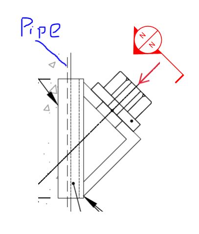
The load is unidirectional and always towards the pipe. the red arrow in my previous sketch is a group of cables that are always exerting compression on the system.
 
@ MGaMart

Thank you so much for the bending check instructions. I was confused about it and even considered using Roarks for flat plates with a whole inside.

Your method is simpler and would save me alot of unnecessary calculations.
 
Yeah, I've been at this a long time and I too would have to step back and do the FBD exercise before diving in.

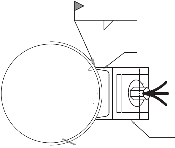
Would you be able to supply an approximate sketch of the view shown below? I understand that the exact details may not be finalized however:

1) as you said, most of these things start their design lives as common practice details and;

2) we gotta start somehwere.

C01_iqkxgf.jpg
 
i do have a view already drawn.

Sorry, i don't know how to make images smaller on this forum.

channel: C200x27.9
angle: 203x203x25.4
view_rcpulh.png
 
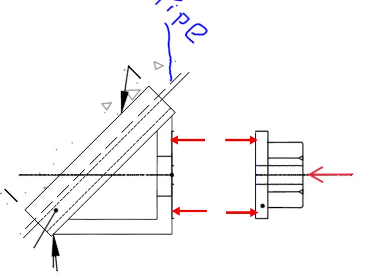
That's about what I figured. As such, I think a good first step is for us to agree on the FBD below: basically that the anchor plate bypasses the upper angle flange in most respects. This should help with your other question about how to design that plate. Whether you go with the yield line method or an elastic, Rourke's method, it's primarily a one way spanning thing. And that agle leg likely doesn't need a flexural check unless it would be appreciably stiffer than the anchor plate. Any disagreement so far?

OP said:
Sorry, i don't know how to make images smaller on this forum.

I quite like the size of your sketch. I've had trouble with sizing in the past too. This is what works for me:

1) Get the image up on my screen at the size that I'd like to see it appear on others' screens.

2) Use the windows snip tool to capture the image and save it someplace for uploading.

C01_vnirrs.jpg
 
Thanks for the FBD.

The drawing is actually to scale. so the loads on the plates are as you draw them (2 equal loads at the edge) instead of one load in the middle (also it's not one cable in the middle, it's a bunch of cables all over the plate).

The angle leg is 25mm while the practice is to use an anchor plate of 19mm. I guess that would make both plates comparably stiff.

The simplified method given by @MGaMart indicates that the angle is failing in bending. so i will go into detail and use the yield line method instead.(also given by @MGaMart).
 
HanStrulo said:
The angle leg is 25mm while the practice is to use an anchor plate of 19mm. I guess that would make both plates comparably stiff.

Even at that, the stiffness of the nut comes into play and should render a flexural check in the upper angle leg either unnecessary or easily passible. The further the loads move to the edges, the less bending you have in that angle leg. You're effectively making your shear spans so short that Bernoulli flexural assumptions don't really apply. Another factor is the rather large hole in the angle leg which is likely for erection tolerance and will reduce stiffness there.
 
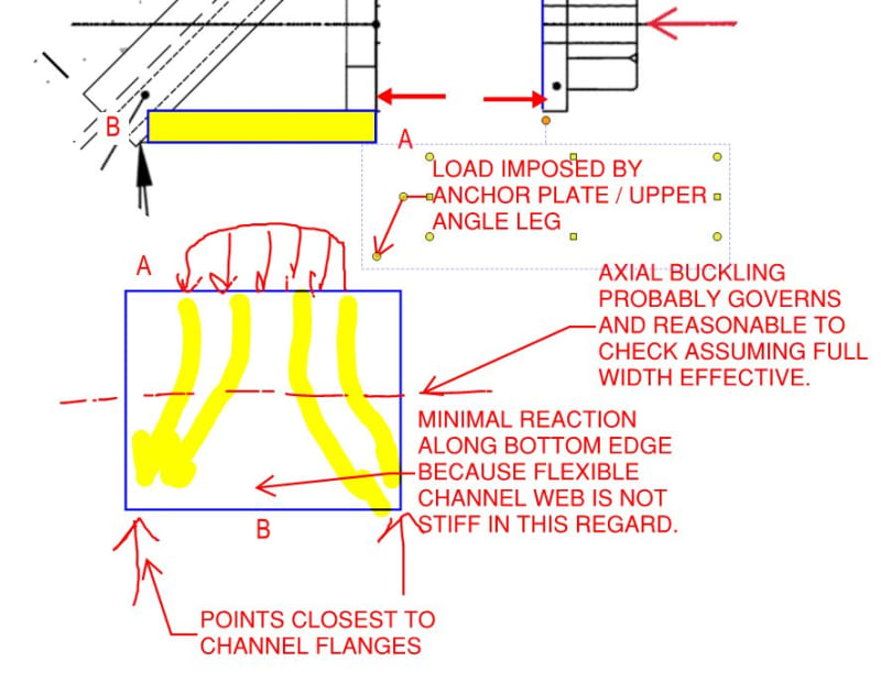
Moving along to the next step, any disagreement regarding the FBD of the lower angle leg as predominantly an axially loaded member? It will have some bending in it of course.

C01_boxnai.jpg
 
yes. for this step, i checked the leg angle for axial compression considering the angle leg length as the unbraced length. the utilization ratio was about 50%.

I think where i am lacking, is not being able to visualize the load path due to different stiffness and boundary conditions.
 
HanStrulo said:
also it's not one cable in the middle, it's a bunch of cables all over the plate

You gotta find some way to tell us what this thing actually is. Is there some english language terminology that we could use to google this? It's starting to sound like anchorage for a post tensioning strand made up of multiple wires. What is the purpose of this concrete filled pipe? Is it an earth retention system of some kind?
 
Yes you are 100% correct. it's my first time designing one. it's a tie back anchoring system (strand anchor).
 
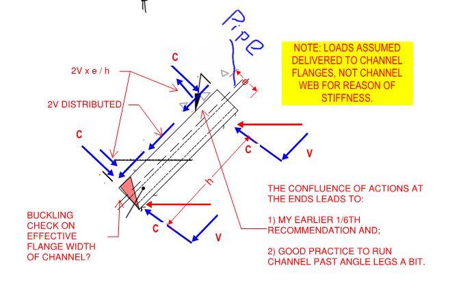
Okay, so here's what I come up with for the channel itself.

C01_rkrgr1.jpg
 
HanStrulo said:
it's my first time designing one.

Me too, we'll learn together.

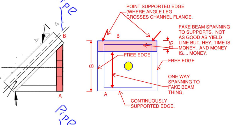
I guess the upper angle leg deserves some attention too.

C01_v5ufjq.jpg
 
Status
Not open for further replies.

Part and Inventory Search

Sponsor