Continue to Site

Eng-Tips is the largest engineering community on the Internet

Intelligent Work Forums for Engineering Professionals

  • Congratulations KootK on being selected by the Eng-Tips community for having the most helpful posts in the forums last week. Way to Go!

Eccentric load on weld groups 2

Status
Not open for further replies.

HanStrulo

Civil/Environmental
Apr 16, 2021
117
HI Everyone,

For anyone familiar with both AISC and CISC. I have a question.

Table 8-4 of AISC gives the coefficient C for eccentrically loaded weld groups (out of plan force and at an angle of 45 degrees).

I looked in CISC and could not find a similar table. The closest i could find was table 3-27 but it's for in-plan eccentric vertical load).

Did i miss something? what is recommended to do in this case?

Thanks
 
Replies continue below

Recommended for you

Thanks. that was very helpful.

For the channel, all the load paths you drew make sense to me.

I have checked the channel for axial compression with an unbraced length= flange width but the cross section i have considered is the flange thickness x 1/2 the length of the channel (i did not know what length to consider so i just assumed half the channel length will help in compression ???).

For the shear, I have checked it as you have described and surprisingly, the channel is experiencing alot of stress because of it (utilization ratio of 73%)

My question is: what length would you have considered the compression check to be done with? was my assumption ok?
 
@KootK

For the last sketch you made, it's really helpful to understand how the plate is configured.

Since i will not check the angle for bending, I tried just now to check the anchor plate (above it) as a beam in bending and it gives me unrealistic thickness requirements. I think i need to just give up and try the yield line method from the AISC.
 
HanStrulo said:
For the last sketch you made, it's really helpful to understand how the plate is configured.

So show me.

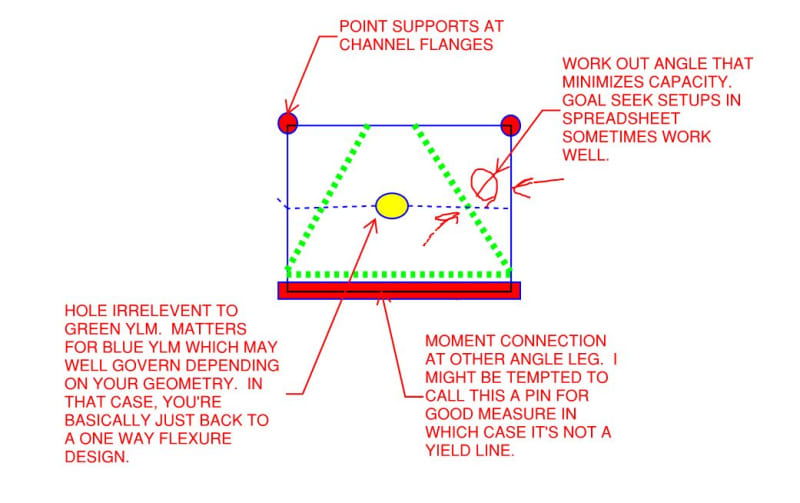
If it's needed, I don't see why you couldn't use both the anchor plate and angle leg in flexure in tandem (non-compositely). But yeah, I like yield line too so all the more power to you on that. Just make sure that it's a yield line pattern compatible with my free body diagram. The choice of method doesn't change the truth of that.
 
KootK's FBDs look to be right on the money, but there is one item that I would add. It is possible to eliminate that moment at the pipe wall by simply ensuring the weld center of gravity coincides with the line of action of the strand cable. With how the FBD is set up, you can see that there is more weld length above the line of action than there is below. Ensure the channel length is equally divided above and below where the line of action intersects the weld interface between channel and pipe and eliminate the moment.

As for the angle bending, the 19mm plate is a great benefit to the yield line analysis as it pushes the yield lines closer towards the supports (which is good thing). In terms of bending, the 19mm plate should only be viewed as a mechanism to better disperse the load into the 25mm angle leg and as just mentioned, modify the yield line mechanism. The yield line analysis should be solely based on the 25mm angle since (as KootK rightly pointed out), the angle and plate are non-composite.

KootK also correctly addressed another item of concern and that is weld stress non-uniformity at the angle-channel interface. This concept occurs quite frequently in (rectangular) HSS wall design with transverse plates, where the load is naturally attracted to propagate to the welds closer the side walls than at the middle of the connecting face. Effective length parameters are usually employed to combat this. A common effective length (Le) applied is Le = (10/(B/t))x(B) where B is the HSS width (in your case, the channel depth) and t is the wall thickness (in your case, conservatively the channel web thickness)(for obvious reasons, Le cannot be greater than B). For tension scenarios, this effective length is what should be used in determining a suitable weld size as well as ensuring the angle thickness is adequate based on the weld size required. For compression scenarios, you could develop the weld for this force or rely on contact bearing if properly fabricated.

Clearly the intent of the channel is to provide a flat surface of which to affix the 203x203x25 angle, but is this detail also necessary to provide minimum clearance to install the nut between the angle and pipe? I have to say that with the geometry selected, there is compounding inefficiencies that may make eliminating the channel a more suitable approach (i.e. weld the angle directly to the pipe). Yes, the angle would need to be profiled to fit the pipe, but for the fact that the angle may already need to be prepared to properly mate with the channel (assuming the detail you showed is correct and the toes are bevelled to accept fillet welds), can't you go one step further and profile the legs to fit the pipe directly? The extra welding saved (as the welds would now be much more efficiently utilized...angle-to-pipe directly) should likely more than offset the profiling operation. If the pipe is in fact concrete-filled (I completely missed seeing that in the sketch), and the system is compression only, there isn't as great of a concern of pipe limit states being violated, and thus trying to disperse the load over a larger region into the pipe may not be warranted. If nut installation is an issue, why not go with a L254x254x25 or even a L305x305x25 and cut down the legs to what works? The yield line analysis still needs to be conducted in my opinion, but it will vastly simplify the design and eliminate the "keep me up at night" variables that plague some of our minds when dealing with connections that are out of our comfort zone.
 
@Kookt

I will let you know of what i get when i use the yield line method. I am not familiar with the section MGaMart mentioned so i am reading it now.

@MGaMart

Your idea of removing the channel could actually help me alot and save up but everyone has been using this configurations for countless jobs before and they will not accept the channel removed. For them, it's tested and proven. All i was tasked to do was to check its integrity as it is.
 
HanSturlo said:
I will let you know of what i get when i use the yield line method.

I think that I may have misinterpreted one of your previous statements. I thought you were saying that I needed additional information about the plate configuration in order to analyze it. I'd be curious to see what you select for your YLM model though. I often find that step to be non-obvious in a lot of non-trivial situations. I do have a picture in mind but I don't want that to taint your first stab at it since I may well be wrong.
 
@KootK

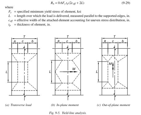
I am not doing any model for the YLM since i don't know how they will be with a rectangular plate with a hole inside. I am just using the formula from the figure 9-5 of the AISC and comparing the available shear strength Rn with my applied load.

Any other thoughts are most welcome
 
What version of the AISC manual are you using? With that information in hand, I can check out that equation and report back any insights that I may think I have. Given how many times YLM has been mentioned in this thread, I feel that we'd be remiss not to kick around some ideas on that. I guess I'll go first and risk the ensuing humiliation of being wrong. I'm mostly here to learn anyhow.

C01_f5sedn.jpg
 
I am using the 15th edition of the SCM.

So what i understand from the yield line method, once the yield lines have been established ( i will use the green lines from your sketch at 45 degree angle), i just need to solve for M using external work=internal work.
 
HanStrulo said:
So what i understand from the yield line method, once the yield lines have been established ( i will use the green lines from your sketch at 45 degree angle), i just need to solve for M using external work=internal work.

Mostly right. It's important to recognize that YLM is an upper bound capacity estimation method when what we normally like as engineers is a lower bound capacity estimation method. The consequence of that is that you often have to futz around with your YLM model geometry to ensure that there isn't a version that would predict a lower capacity than the version(s) that you've been studying. I don't know with certainty that 45 deg angles gets you that in my model. That's why, in my sketch, I suggested that it was a parameter in need of examination.

And, like I said earlier, it may well be the blue yield line pattern that governs this.

I checked out figure 9-5. I would say that, in general, the method described there works. At the same time, I don't feel that any of the yield line models actually shown in that figure are a logical fit for your design situation.

C01_kno52z.jpg
 
@ KootK

I am using the yield lines you have drawn in green to calculate the yield moment. I noticed that my hole diameter is actually quite big and anything will have to go through it.

I don't know if i should ignore that fact and consider it intact.

 
I think that you need to consider it for the BLUE yield line mechanism which may well govern over the green.

As always, if you post a good sketch of your situation, the answers that you receive are likely to improve.
 
You are right. But considering the blue mechanism, solving external work=internal work for M is not possible

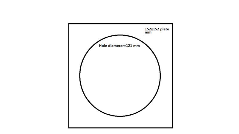
This is the true dimensions of the whole and plate.

hole_and_plate_jzek82.png
 
Oh my... that's going to be pretty much worthless.

What's the nut thing look like for this?

What's the hole in the angle look like? It may be all that you really have to work with here other than whatever load spread the nut thing may give you.

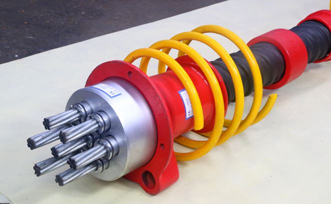
Any chance you could scare up a pic of the anchor?
 
Yes. that is exactly it. the dimensions are also accurate.

The plate dimensions are standard for this type of strand anchor as i understand.
 
As I see it, you pretty much need to span that first span in the load path with the nut itself. If so, YLM will not be a useful tool for this part of the design and I see the beginning of your load path behaving more like the sketch below.

C01_q8gssb.jpg
 
So this is what you're analyzing, just with a pipe instead of a spreader plate? Are we safe to assume the 121mm hole diameter is common to the anchor plate, the angle, the channel and the pipe?

Smart-House-Caisson-wall_aqpq0q.jpg
 
@ Kookt @MGaMart

I apologize, i was away from the digital world for the weekend.

@MGaMart

it is common practice to use 7 strands with the configuration i have shown and some people i work with do it as the norm.

I added 2 more strands so i am stretching it a bit.
 
@KootK

Sorry if this question is a bit late, but i remembered the load path and the checks associated with it and I am a bit confused on one last thing.

For the channel flange, should I check it against flange yielding, crippling? these are usually done for the web because they are usually loaded on the flange, but in this case, the channel is loaded on the web.

 
Status
Not open for further replies.

Part and Inventory Search

Sponsor