Continue to Site

Eng-Tips is the largest engineering community on the Internet

Intelligent Work Forums for Engineering Professionals

  • Congratulations KootK on being selected by the Eng-Tips community for having the most helpful posts in the forums last week. Way to Go!

Effect of datum precedence

Status
Not open for further replies.

vanquang

Mechanical
Apr 30, 2018
15
Snap3_s8iwyw.jpg

Snap5_dymk9y.jpg

Snap6_pdwzei.jpg

Hello everyone
I don’t undertsand about the precedence of reference datum in this drawing.
I asked my colleague and he just say it obeys principle of MMC.
I wonder without regarding to MMC, is there any difference if I change the order of reference datum in tolerance frame.(X,A,C to A,C,X)
 
Replies continue below

Recommended for you

Yes -- the difference is that you would be changing the datum precedence. Namely, you'd be changing the primary, secondary, and tertiary sequence.

John-Paul Belanger
Certified Sr. GD&T Professional
Geometric Learning Systems
 
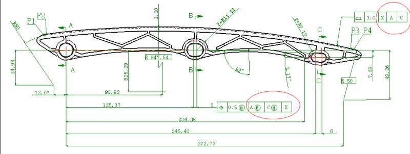
The datum referencing is entirely messed up. The location of datum feature B depends on the location of datum feature C which depends on the location of datum feature B which depends on ...

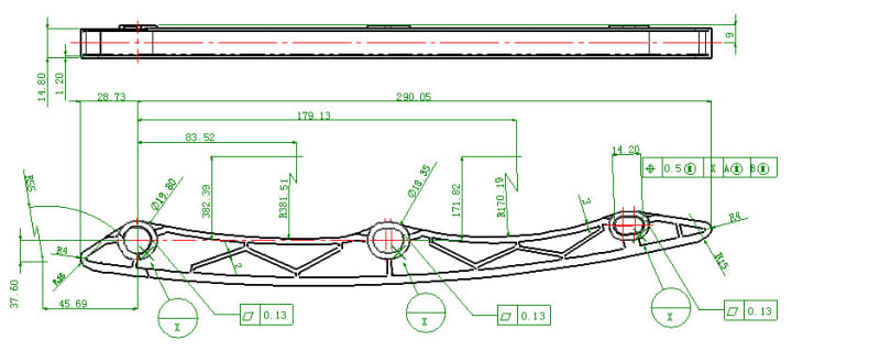
The targets for X are nearly colinear, so small variations in the surface will cause large variations in the rotation of the part.

It's like someone has written 2 + 4 = 24.
 
Belanger said:
[/ Namely, you'd be changing the primary, secondary, and tertiary sequence]
I don't understand your explanation. The primary, secondary, and tertiary are create reference frame. Will changing the datum precedence affect to reference frame.
 
here we go again, i see you've posted this exact drawing again in yet another forum with a slightly different set of questions. i wonder if i'll end up seeing this in another forum that i frequent.


also the photo you posted in your other duplicate thread (fig 4-18 in the 1994 standard and 4-20/4-21 in the 2009 standard) does a decent job of illustrating what changing around the datum precedence does to how a part would be measured/inspected and therefore how the features of that part could change depending on how the datum reference frame is set up. allowable variation of a part and its features can change quite significantly as a result.


3DDave - nice catch with the infinite looping (recursive??) datums. i didn't take a very close look at the drawing on the first go around as the thread was a bit of a mess...
 
Look also at
Irregular Datum Features of Size

Irregular datum features of size is a new concept illustrated and explained in the latest revision of the Geometric Dimension and Tolerancing standard.

Datum Features of Size

Where a datum feature symbol is placed in line with a dimension line or on a feature control frame associated with a feature of size, the entire feature of size is the datum feature.

Datum Sequencing

Consider this sentence. ''The dog walked I.'' We know something is wrong: either the order is incorrect or the personal pronoun is the incorrect part of speech. Depending on your assumption, you might interpret this sentence in one of two ways, ''I walked the dog'' or ''The dog walked me.''

In the same way, when datum features are incorrectly sequenced, the tolerance is ambiguous. I frequently see drawings that have datum features specified in feature control frames in an order of precedence that makes no sense. Proper datum sequencing is extremely important to insure that only one, correct interpretation is possible. The attached excerpt from my book will help clarify this subject.

Datum Feature Identification

All datum features must be specified in order of precedence. Each datum feature must be identified with a datum feature symbol. Datum feature symbols must not be applied to centerlines, center planes, or axes.

I often see drawings with datum feature symbols attached to axes or center planes, and I sometimes have difficulty convincing engineers that it is impossible for inspectors to orient or locate features relative to imaginary lines and planes. The discussion on the attached file will help clarify this issue.
 
The 0.13 flatness refinement of the 0.13 parallel requirement adds nothing. If a surface must be in a bandwidth of 0.13 then it is already being forced to be flat to that same amount. You get flatness "for free" with you parallel requirement.

The perpendicular refinements to position need to come below the position FCFs.
 
Quote:"I have 2 dimensions with positional tolerance and profile tolerance. But I don’t understand exactly the meaning of them and the role of them when manufacturing."

Quote:"I am concerned about frame reference. In the original picture, with the profile tolerance the datum precedence is X,A, C and for position tolerance is A,C, X. I wonder the frame reference which are setup in those cases are same or different."

One of the questions I have is: what would be the physical reality of this assembly ? How this part go together with its mating components? Why this part acts X -primary--then A -secondary--and then C -tertiary--for one feature AND the same rigit part --solid part acts A-primary then C secondary and X tertiary? Most likely only one datum precedence is the correct one. I suspect X primary, A secondary and C tertiary is the corect one. I am just guessing.

It is all about arresting/stopping the defrees of freedom. X primary--flat surface/plane stops 3 degrees of freedom and then A secondary stops another 2 and for C tertiary is left only one.
All the other features on the same part should (I say should, not shall) be defined based on this coordinate system. X, A and C.

If multiple FCF's are used (X, A and C for one feature then A, C and X for other feature ) multiple setups for measurements are needed. each and every datum features will arrest different degrees of freedom based on their precedence.

Talk with the designer and ask him/her why the datum precedence is wondering around and again what would be the physical reality of this part.
 
greenimi said:
[/ X primary--flat surface/plane stops 3 degrees of freedom and then A secondary stops another 2 and for C tertiary is left only one. ]
May you explain for me how A stop another 2 and C is left only one. I can only understand easily that X is a plan and it is control 3 degree, but about A and C, i don't know what they should be to control the rest degrees
 
The part has 6 degrees of freedom (DOF's): 3 translations and 3 rotations.

X -used primary- as a planar surface will stop 2 rotations and 1 translation. Remaining 1 rotation and 2 translations
A-used secondary-- FROM the remaining DOF's -- will stop those 2 translations left ---Cannot physically stop the remaining rotation (because it is a cylinder)
C-used tertiary --FROM the "new remaining" -- will stop the remaning rotation "c" is the width of the slot. The length of the slot should be positioned to X, A and C (in this order of precedence)

In my opinion, but I do not know much about the functionality of this part, C and B should be the width of their respective slot, used only to stop the remaining rotation and to be referenced in their respective FCF's only for the length of the slots (as a tertiary in the position callout)

 
greenimi said:
[/X -used primary- as a planar surface will stop 2 rotations and 1 translation. Remaining 1 rotation and 2 translations
A-used secondary-- FROM the remaining DOF's -- will stop those 2 translations left ---Cannot physically stop the remaining rotation (because it is a cylinder)
C-used tertiary --FROM the "new remaining" -- will stop the remaning rotation "c" is the width of the slot. The length of the slot should be positioned to X, A and C (in this order of precedence)
]
So, to establish datum reference frame; I will have datum plane X, datum axis A and C is datum center plane C which is parallel with datum axis A. Is it right?
 
Center plane C should be located basic to datum axis A. Datum feature simulator of datum feature C (maximum material boundary width perpendicular to datum plane X--IF C is called at MMB--).
If C is called at RMB, then datum feature simulator of datum feature C, parallel planes at maximum separation perpendicular to datum plane X, center plane located basic to datum axis A.

And datum feature simulator of datum feature A = largest inscribed cylinder perpendicular to datum plane X, if A is callout RMB.

All of the above will give you 3 mutual perpendicular planes which will be your datum reference frame: datum plane X, datum axis A and datum center plane C.

 
Status
Not open for further replies.

Part and Inventory Search

Sponsor