Continue to Site

Eng-Tips is the largest engineering community on the Internet

Intelligent Work Forums for Engineering Professionals

  • Congratulations KootK on being selected by the Eng-Tips community for having the most helpful posts in the forums last week. Way to Go!

Effective width for fasteners 10

Status
Not open for further replies.

dik

Structural
Apr 13, 2001
25,673
When using a high strength bolt clamping two pieces of metal together. What effective width do you use on each side of the bolt hole to determine the effective flexural width? Is there a value prescribed by code? or by common useage? I typically consider 4 x the thickness of the material on each side for a total of 8 x the thickness.

For a 1/4" thick plate, I would normally use an effective width of 2".

-----*****-----
So strange to see the singularity approaching while the entire planet is rapidly turning into a hellscape. -John Coates

-Dik
 
Replies continue below

Recommended for you

The way I was taught and have done it ever since is to consider a shear angle.
For example, if you have a 6" square HSS and a base plate with bolts at 9" each way, the distance from the center of the bolt to the HSS is approximately 1.5"xsqrt(2)=2.12". The approximation neglects the bend radius at the corner of the tube. If the shear angle is 45 degrees, then the effective width is (2)x(2.12)=4.14". Some might consider 45 degrees as unconservative. If the shear angle were 30 degrees, the effective width would be 2.45".

1/4" plate with HSB??
 
Thanks... the bolt is in a metal base plate securing a post, with gusset plates. The span is the distance between the gusset plates with the bolt located at mid span. I'm assuming the width of the section as 8x the thickness to determine the plastic section to develop the moment resistance of the base plate.

-----*****-----
So strange to see the singularity approaching while the entire planet is rapidly turning into a hellscape. -John Coates

-Dik
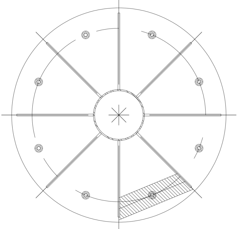
 
This is the condition.

Bolt_Circle_eur9z9.png


-----*****-----
So strange to see the singularity approaching while the entire planet is rapidly turning into a hellscape. -John Coates

-Dik
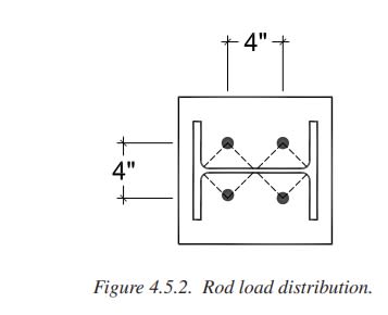
 
dik,
where is the applied moment?
and how are you getting flexure at the fastener line with the gusset plates there?
 
At the post and it is transferred to the bolt circle and anchor rods.

-----*****-----
So strange to see the singularity approaching while the entire planet is rapidly turning into a hellscape. -John Coates

-Dik
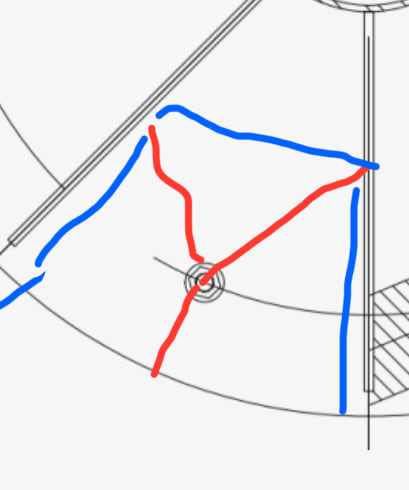
 
ok, so with a moment on the post,
on one side the fastener is in tension, which pulls down on the base plate; more of a pull thru condition than overall bending of the base plate,
on the other side there is contact between the base plate and ground, so there is a distributed pressure on the bottom of the base plate,
the gussets stiffen the base plate, so the critical bending section probably is a line connecting the ends of two gussets, but there is not much pressure outboard of that line to bend the plate,
so doesn't seem like the base plate would fail in bending before a compression crippling failure of the gussets or tensile pull thru at a fastener.
 
The gussets can be designed to accommodate the bolt/moment forces. What I'm wondering is the effective width to use for calculating the moment resistance of the base plate.

-----*****-----
So strange to see the singularity approaching while the entire planet is rapidly turning into a hellscape. -John Coates

-Dik
 
Just checked DG 1, and can't find anything...

-----*****-----
So strange to see the singularity approaching while the entire planet is rapidly turning into a hellscape. -John Coates

-Dik
 
Need BA’s yield line knowledge but with the gusset configuration this seems like an appropriate yield pattern:
IMG_9416_o5ua59.jpg
 
Thanks Celt... I'd normally do a yield line solution; I was looking for a quick simple solution... just a span and a tributary width to calculate the Mp... The span seems simple enough and I usually use 8x thickness for a trib width. I was wondering if others had any other trib widths.

-----*****-----
So strange to see the singularity approaching while the entire planet is rapidly turning into a hellscape. -John Coates

-Dik
 
the failure lines that Celt drew are only for the location where fastener is in tension. but I still doubt those locations are more critical than pull thru of the fastener thru the plate locally or failure of the fastener in tension.

 
The fasteners will not go into compression... Base plate and gussets look after that.

-----*****-----
So strange to see the singularity approaching while the entire planet is rapidly turning into a hellscape. -John Coates

-Dik
 

IMO, 6t is more reasonable. I agree with Celt83 (Structural) solving with yield lines and a PBS for his post.
We are at the other side of ocean . The approach in Euro Zone at the attached doc.


According to the grace of God which is given
unto me, as a wise masterbuilder, I have laid the foundation, and another buildeth thereon. . . .
I Corinthians 3:10
 
 https://files.engineering.com/getfile.aspx?folder=b07064bf-a4b5-4713-a63b-c160058450e3&file=07-GB_Column_Bases.pdf
Thanks... it works with 6xt also... If I had lots of them to do, I'd use a yield line approach...

and a BPS for your's too...

-----*****-----
So strange to see the singularity approaching while the entire planet is rapidly turning into a hellscape. -John Coates

-Dik
 
dvd... I cannot open the file... thanks...

-----*****-----
So strange to see the singularity approaching while the entire planet is rapidly turning into a hellscape. -John Coates

-Dik
 
Status
Not open for further replies.

Part and Inventory Search

Sponsor