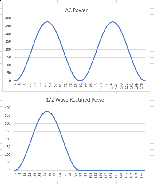
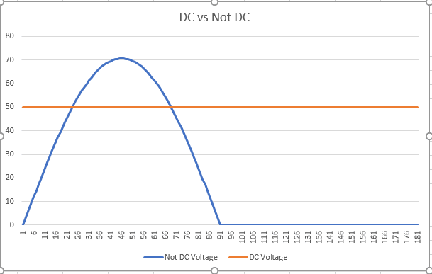
This thread has been challenging. As previously stated, I have replied, as always, from experience and that experience is that in an industrial setting a rectifier's output is considered to be DC and is measured with instruments on the DC setting. I cannot, from experience, vouch for the academic viewpoint that the output is RMS DC (?) as is espoused here nor, as stated, have I ever attempted to measure the output of a rectifier with meters set to AC. For those that wonder what this statement means, yes, I am an engineer but no, I was not taught to analyze rectifier circuits using RMS DC.
Having said that, I have also conceded that the question of considering the rectifier output to be RMS DC is an interesting one to consider, especially in the case of a resistor. However, the fact that I am seeing very few other posters conceding that the DC viewpoint is valid in an industrial setting leads me to believe that there is not a lot of direct experience with rectifiers reflected in this thread. I am in agreement with Edison123, the guy who posted on 28 Jun 19 12:01 that he had actually built a circuit and tested it.
This being said, I am done. To those that read this thread, as always, caveat emptor.
![[bigsmile]](/data/assets/smilies/bigsmile.gif "[bigsmile] [bigsmile]")

![[blush]](/data/assets/smilies/blush.gif "[blush] [blush]")