Continue to Site

Eng-Tips is the largest engineering community on the Internet

Intelligent Work Forums for Engineering Professionals

  • Congratulations pierreick on being selected by the Eng-Tips community for having the most helpful posts in the forums last week. Way to Go!

Electrical noise from VFD affecting Temperature Probe 2

Status
Not open for further replies.

veryconfused

Agricultural
Jul 15, 2021
25
Firstly, I have no idea if I am posting this question in the correct forum, hopefully it's correct. Secondly, I am not an engineer in anyway. I have an issue with EMI from a 3 phase 480v VFD affecting a shielded temperature probe and was hoping somebody on the forum might be able to offer some advice on how to solve my issue.

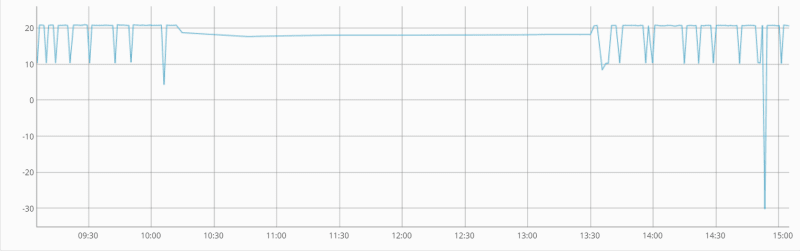
If I leave the temp probe hanging in the air then the EMI has no affect on the temperature reading. However, as soon as I put the temp probe into the water I start getting temperature spikes. If I only needed to measure the air temp things would be fine, sadly this is not the case.

Does anybody have any ideas on how I might fix this issue? I have ordered some ferrite rings to install on the output side of the VFD. Also, I tried placing a small metal rod in the sump and grounding it with a wire but that hasn't helped.

Any help/advice would be greatly appreciated.

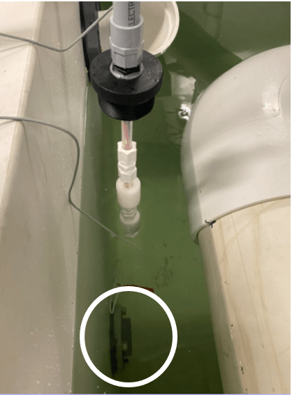
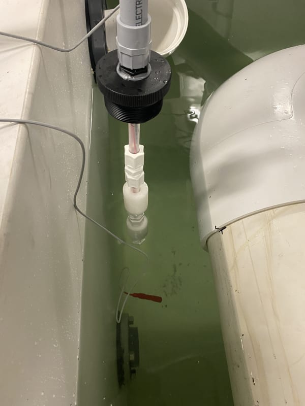
You can see the red temp probe in this image
IMG_4015_uzix9o.jpg

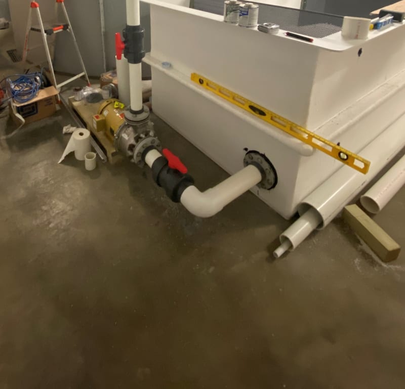
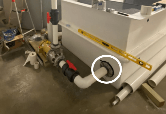
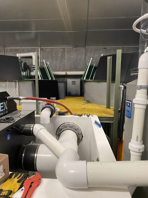
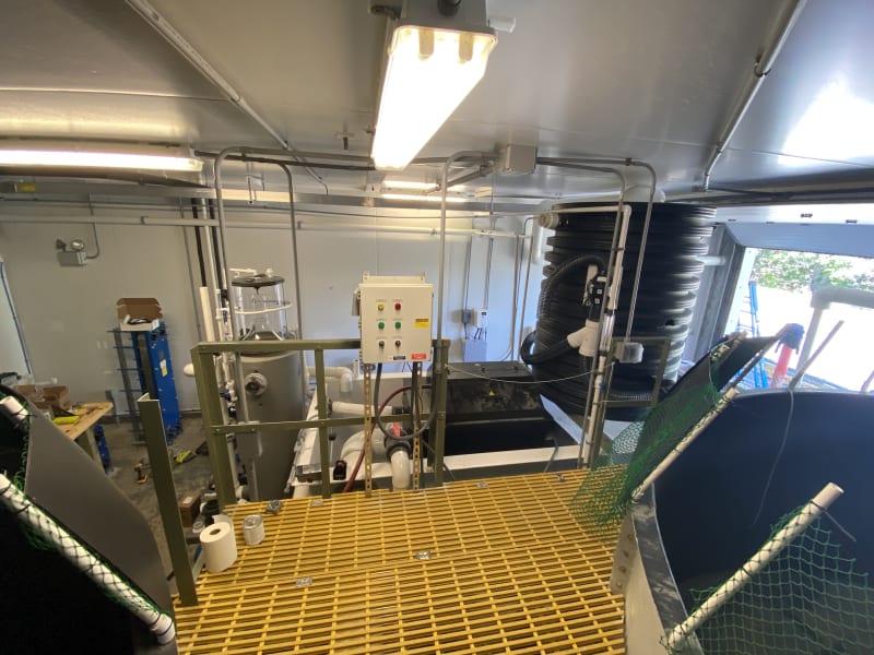
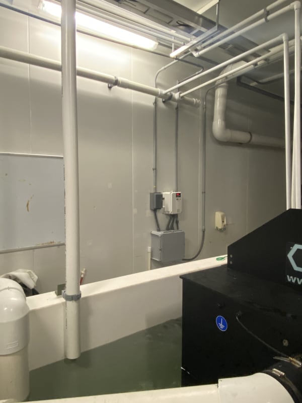
Position of VFD relative to temp probe
IMG_4016_er4avf.jpg

Graph showing temp probe in and out of the water.
Temp_probe_graph_hvcigx.png
 
Replies continue below

Recommended for you

Electricpete - No submersible pump. This is the location of the pump that is connected to the VFD. I will try a grounded can or something around the probe to see if that helps.

I did drop in some stainless steel rods into the sump and grounded those, however, that didn't help. I wonder if moving the probe closer to the grounded rods might help. I will try that.

Pump_mtht9y.jpg
of the main pump that runs of the VFD.
 
Are the pipe passages on the pictures the same ones from the outside and from the inside.
image_rket8z.png

image_jnxkon.png


And what is this ??
image_hwbq6i.png


Best Regards A

“Logic will get you from A to Z; imagination will get you everywhere.“
Albert Einstein
 
The pipe passage you can see below the temp probe is for another pump, not pictured. That pump is not on a VFD and has not been running at all

The black thing, is a drum filter.
 
Okey is the probe that you are having problems with near this drum filter or does the tank with the VFD drive not have one of those?

/A

“Logic will get you from A to Z; imagination will get you everywhere.“
Albert Einstein
 
Wow that's weird for the pump/motor outside the tank seemingly influencing water which seems to be influencing probe inside the tank.

I guess we have to suspect (?) that high frequency seen on the stator is either conducted direct to pump casing from stator frame or else it is coupled from motor stator to motor rotor which in turn might have some kind of electrical connection to the pump impeller. (do you happen to know the coupling type).

Under that theory, to my simple thinking, the highest magnitude of this HF voltage-with-respect to ground would be highest at the pump (casing or impeller) and voltage would taper towards 0 everywhere that you have a good ground. The more well grounded surfaces it has to go past before getting to probe the better.

Is the tank itself grounded? It seems like it should be. I like the idea of putting a can around the probe. If you can't do that I might be tempted to try grounding suction and discharge flanges associated with this pump, either directly at the pump or where they penetrate the tank. I guess flat braided style groundstrap for high frequency would be best if you have something like that, but I wouldn't let that stop me from trying whatever I had available.

If you're inclined toward troubleshooting maybe put a meter to check resistance to ground from tank (if it's a metal painted tank you have to find access to unpainted area). And check resistance from ground to pump flange (easy access there, no paint). It would be even more interesting to see if you can find evidence of induced voltage on the pump flanges. A a voltmeter to ground in total rms mode would be a start (would include high frequency as well as lower frequencies).

=====================================
(2B)+(2B)' ?
 
Redsnake - yes, the probe is near the drum filter. I’m not quite sure what you mean with the second part of your question.

Electricpete - not sure what you mean by coupling type. You need to dumb things down for me.
The tank itself isn’t grounded. I did bundle some stainless pipe together and put it in the sump which I grounded. If that’s what you mean?

The tank is made of fiberglass. The only metal parts are the pump and motor and the bolts for the flanges

I will try out some of the things you have suggested later this week.
 
I was wondering if the the motor with VFD drive is supplying the same tank that has the drum filter?
And that is the tank where the probe problem is.
And this drum filter is powered with a ordinary motor I suspect.

Electricpete, i think the VFD drive induces a magnet field around the motor this electric field can damage the bearings in a motor if they are not made for this type of application, which is a whole other discussion.
This induced magnetic field will fluctuate with the VFDs regulation of the motor.
Since the motor are mechanically connected to the pump that is also made of iron the magnetic field will also expand on to the pump.
And since salt water are better at transmitting magnetic fields then fresh water that are dimagnetic (repelling magnetic fields) I think that it is possible that this is the source of the disturbances.
It might even be possible that the magnetic field might go through the glasfiber tank and get in that way.

You know this test pens AC Voltage Detector that is used for finding cables inside walls with a lamp that lits up.

veryconfused if you can get your hands on one of those you might be able to see how fare the magnetic field can reach.

image_ynjf7f.png


If I am right it will not help containing the probe in something that can be magnetized.

This is me half WAG = wild-ass-guessing. ;-)

Best Regards Anna


“Logic will get you from A to Z; imagination will get you everywhere.“
Albert Einstein
 
Silicone is highly permeable to water and water vapor. Not a very good choice for submersion. Putting the probe into a stainless sheath might work better.
 
Redsnake - the water is pumped from the white tank you see in the photo into two tanks next to it. The water then flows out of these tanks into the drum filter that is sat on a fiberglass stand in the white tank. The drum filter has a small motor that turns the drum when needed.

Do you think putting the probe in some kind of faraday cage would help?

To give you an idea of how far this magnetic field reaches, if I put the probe in one of the other tanks I get the exact same issue. It’s weird.

I do have an AC voltage detector, so that’s something I can try.

This images shows to two other tanks.
DD066788-6C44-4796-8DD0-5B6D5A1BCB15_gpn8nr.jpg


08D96396-BBA3-40FA-9FD3-35396A4C39DA_navj41.jpg
 
> And since salt water are better at transmitting magnetic fields then fresh water that are dimagnetic (repelling magnetic fields) I think that it is possible that this is the source of the disturbances

Fresh water is diamagnetic yes with relative permeability 0.999992. Pretty darned close to 1.0 as we see in a vacuum. Salt moves it closer to 1.0? So max change 0.00008 if I'm understanding correctly. It hardly seems that would be significant. I'm probably not understanding what you're saying. I'm not seeing any scenario where water plays any role in magnetic / inductive interference.

I lean very much towards capactive / electric coupling and away from inductive / magnetic coupling as a cause for this interference.

For capacitive/electric interference, we know there are often high frequency components of the voltage (especially common mode voltage) that can be coupled onto the stator frame and the rotor. Their high frequency means they are easily capacitively coupled. The fiberglass tank and pvc pipes mean they can travel far before being dragged towards ground. Water does indeed cause a big change in electrical permittivity (factor of 80) from air which could explain why removing it from the water makes a big difference.

For inductive/magnetic interference, the motor inductance tends to be a low pass filter so that the high frequency components of voltage do not as much pass into the current, so less high frequency magnetic. Magnetic is also limited by by routing equal/opposite currents together at the source, shielding by motor frame and conduit. And we limit inductive interference by twisting the leads of the target (not much loop area). Also flux flows in loops, I'm not picturing any loop flow out and back through the water that would allow high flux density at the probe. Magnetic permeability barely changes at all between air and water as far as I can tell (unlike electrical permeability which changes by factor of 80). The bottom line I just can't visualize what the water has to do with inductive / magnetic interference. Maybe eddy currents flowing in the salt water, that's the closest thing I can imagine.

We didn't talk about resistive but I lump that in with capacitive. At least they both would presumably involve an ac voltage distibution in the water which is highest at the pump and decreased by introducing ground in the water.

Just my thoughts fwiw, I may be way off base.

ps some guy named electricpete1 made a video on diamagnetic properties of water once

=====================================
(2B)+(2B)' ?
 
And yet we don't even know if the water is live.


You guys are offering band-aids to slap onto a potential disaster. Grounding a fiberglass tank? A can around a probe in a liquid conductor? Ground rods?


2hzhahw.gif


Keith Cress
kcress -
 
Itsmoked - What could cause the water to be live?
It’s certainly something I could rule out. When the sump was full and the motor was running I had my hand in the tank multiple times. I’d be very surprised if the water was live. Still something to check
 
> And yet we don't even know if the water is live.

If water is live with power voltage, then you're suggesting motor shorted to frame and did not trip. Then the motor frame and pump are also live. That's a hazard right off the bat, not related to anything we suggested. And it's a far bigger hazard at the motor than in the tank. But it's unlikely since we protect against this hazard with motor trips and equipment safety grounds on the motor.

> Grounding a fiberglass tank?

I asked what material the tank was in the same post that I suggested grounding the tank. It was only in the response after that we found out it was fiberglass. Ground connection would have no beneficial nor adverse effect on a fiberglass tank.

> A can around a probe in a liquid conductor? Ground rods?

Any equipment safety grounds added between otherwise floating parts and local safety ground bus should only serve to increase personnel safety.

I also suggested to add grounded structure in the tank, which would include some kind of barrier or the can. I don't see the context where your term "ground rods" arises (I never said anything about ground rod). op put steel rods into the sump, which I assume were laid down (not driven) with a cable attached running to safety ground bus. I don't see a big problem with that other than it's ugly and it may corrode or cause other fluid-system related problems. If it didn't fix the problem I hope he took them out.

Any ground connection I mentioned should be connected to safety ground system, not to any neutral.

That's the way I see it. As always I could be mistaken. Feel free to elaborate.

To help check for the dangerous situations you suggest, op could use a voltmeter probing for voltages to ground.

=====================================
(2B)+(2B)' ?
 
Is the pump metal? If so that's a fine connection to the pumped fluid.

I see all sorts of equipment around the tank, any of it could be conducting to the brine.


Pete; Adding a ground rod to a tank of water is a bad idea. If there is a current source you will be doing extensive electrochemistry in the tank and fluid screwing up the chemistry and likely killing any biology the system might be supporting. It is a bandaid. You need to correct the leakage problem at its source not set up a current path that can make the system potentially more dangerous as now you've created a potential voltage gradient.

If there is high frequency energy in the brine then it needs to be excluded from the brine.

Keith Cress
kcress -
 
> Is the pump metal? If so that's a fine connection to the pumped fluid.

My response was as above: If water is live with power voltage, then you're suggesting motor shorted to frame and did not trip. Then the motor frame and pump are also live. That's a hazard right off the bat, not related to anything we suggested. And it's a far bigger hazard at the motor than in the tank. But it's unlikely since we protect against this hazard with motor trips and equipment safety grounds on the motor.

> Pete; Adding a ground rod to a tank of water is a bad idea. If there is a current source you will be doing extensive electrochemistry in the tank and fluid screwing up the chemistry and likely killing any biology the system might be supporting. It is a bandaid

Yes, it's a very good point you made that it could have all kinds of bad effects (unrelated to electrical safety) depending on what's going on in the tank.... which I don't think we've been told. I didn't think much about that. (fwiw I did suggest above to remove the rods if they didn't help, but it's good you highlighted that). op - what is the process that goes on in this tank?

> You need to correct the leakage problem at its source not set up a current path that can make the system potentially more dangerous as now you've created a potential voltage gradient.

I don't see that adding a grounded component in the tank increases any tank area personal electrical hazard originating from the vfd / motor. Any voltage difference that is created will be less than the original voltage to ground. But let's wait and hear what the process is, there may be a lot of other good reasons not to put anything in there.

=====================================
(2B)+(2B)' ?
 
In the two tanks next to the white tank we will be adding fish.

I’ll make sure to remove the stainless metal rods that I grounded from the white tank. That didn’t help.

It would be great to discuss this is more detail over the phone but I don’t see anyway to privately contact anyone.

I will add that the pump is properly grounded and protected. I don’t see anyway for it to energize the water without tripping something
 
How's the shaft grounding on the motor? If it's not great, you're grounding it through the pump and the salt water to the probe.

I’ll see your silver lining and raise you two black clouds. - Protection Operations
 
On that note about shaft grounding, make sure all of your sensors and control circuits are ungrounded and all cable shielding is grounded on one end only or not at all. Stray ground current should not be able to find it's way in to your control and measurement circuits if they're not grounded to start with.
 
Status
Not open for further replies.

Part and Inventory Search

Sponsor