Leandro Fernandes
Mechanical
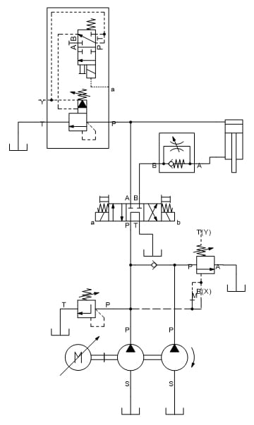
My team is designing a pressure vessel testing machine. This testing machine can be simplified and assumed to be a 120ton hydraulic press with a vertically mounted hydraulic cylinder.
Our goal is to use an HMI to set the force the cylinder shall apply to the test piece. The force range is from 10ton to 120ton. We want the accuracy of the applied force to be +/- 5% of the nominal force set in the HMI. The extension and retraction speed of the cylinder is not relevant.
We are designing the electro-hydraulic circuit for this cylinder and have come across 3 possible solutions to control the pressure on the piston side of the cylinder:
We believe that solution 1) will require a control loop with pressure sensor data feedback to the controller (which, considering also the higher cost of the valve, would make this the most expensive solution).
We are looking at existing solutions and usually they use a proportional pressure regulator valve. We don't mind to use a proportional pressure regulator valve but I am trying to understand if a proportional pressure reducing valve would have any advantage, and if not in which applications would a proportional pressure reducing valve be chosen over a proportional pressure regulator valve?
So, in summary my question is: which possible solution is more appropriate for our application?
Our goal is to use an HMI to set the force the cylinder shall apply to the test piece. The force range is from 10ton to 120ton. We want the accuracy of the applied force to be +/- 5% of the nominal force set in the HMI. The extension and retraction speed of the cylinder is not relevant.
We are designing the electro-hydraulic circuit for this cylinder and have come across 3 possible solutions to control the pressure on the piston side of the cylinder:
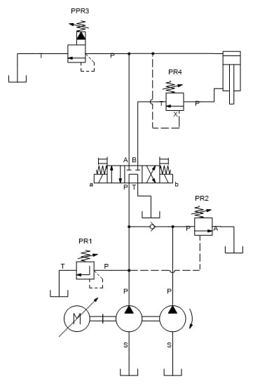
1) Servo directional control valve
2) Proportional pressure regulator valve
3) Proportional pressure reducing valve
We believe that solution 1) will require a control loop with pressure sensor data feedback to the controller (which, considering also the higher cost of the valve, would make this the most expensive solution).
We are looking at existing solutions and usually they use a proportional pressure regulator valve. We don't mind to use a proportional pressure regulator valve but I am trying to understand if a proportional pressure reducing valve would have any advantage, and if not in which applications would a proportional pressure reducing valve be chosen over a proportional pressure regulator valve?
So, in summary my question is: which possible solution is more appropriate for our application?