Continue to Site

Eng-Tips is the largest engineering community on the Internet

Intelligent Work Forums for Engineering Professionals

  • Congratulations waross on being selected by the Eng-Tips community for having the most helpful posts in the forums last week. Way to Go!

Electro-hydraulic pressure control system

Status
Not open for further replies.

Leandro Fernandes

Mechanical
Oct 4, 2018
10
My team is designing a pressure vessel testing machine. This testing machine can be simplified and assumed to be a 120ton hydraulic press with a vertically mounted hydraulic cylinder.

Our goal is to use an HMI to set the force the cylinder shall apply to the test piece. The force range is from 10ton to 120ton. We want the accuracy of the applied force to be +/- 5% of the nominal force set in the HMI. The extension and retraction speed of the cylinder is not relevant.

We are designing the electro-hydraulic circuit for this cylinder and have come across 3 possible solutions to control the pressure on the piston side of the cylinder:
1) Servo directional control valve​
2) Proportional pressure regulator valve​
3) Proportional pressure reducing valve​

We believe that solution 1) will require a control loop with pressure sensor data feedback to the controller (which, considering also the higher cost of the valve, would make this the most expensive solution).
We are looking at existing solutions and usually they use a proportional pressure regulator valve. We don't mind to use a proportional pressure regulator valve but I am trying to understand if a proportional pressure reducing valve would have any advantage, and if not in which applications would a proportional pressure reducing valve be chosen over a proportional pressure regulator valve?

So, in summary my question is: which possible solution is more appropriate for our application?
 
Replies continue below

Recommended for you

You don’t need a servo valve for this application. You would only use a servo valve if you want fast response and a high degree of accuracy. Even the pressure setting is not highly accurate if you can live with +/-5%

Using a pressure reducer or a relief valve is dependent on what other functions are going on and also what type pump you have.

It’s easy to set the pressure. The more difficult part is controlling the losses and the best generation. A relief valve is less efficient, if you have a fixed displacement pump. If you have a pump with a compensator, then it’s very straight forward.

More information on the type of system is needed to give further help.

Certainly no need for a servo valve and closed loop control based on your initial description of the requirements.
 
Another option that may be simpler and less expensive is to use an air driven hydraulic pressure booster. This is a reciprocating pump that has an air piston that is, say, 10 or 20 (or more) times the area of the hydraulic piston, so the hydraulic pressure produced is 10 or 20 times the air pressure supplied. Then an instrument grade air pressure regulator can control your hydraulic pressure.

 
HPost:
We haven't yet chosen the pumps to use. We are discussing if we should use variable displacement pumps with a fixed speed electrical motor or a variable drive fixed displacement pumps.
One colleague argues that fixed displacement pumps become jerky at low drive speeds with output pressure spikes.
We intent to use a max pressure of 350 bar.
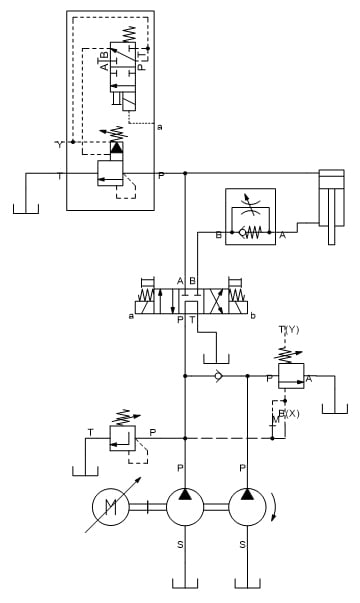
I have attached a simplified diagram of our circuit. I have removed a few details (accumulator, regenerative extension, etc.).
simplified_circuit_y5mwqt.jpg


CompositePro:
It would be very difficult to use an air driven pressure booster. Our hydraulic cylinder has a diameter of 250mm (10") and a stroke of 1m (3 feet).
 
There are inconsistencies in the statements.
My team is designing a pressure vessel testing machine.
This testing machine can be simplified and assumed to be a 120ton hydraulic press
There is a lot of difference between pressuring vessels and making a press that applies force.

The diagram looks like a press.
If so then a pressure regulator or pressure relief valve is not the way to make a press.
These devices do not take into account the pressure and opposing force of the oil on the rod side of the cylinder.

To control the applied force of a press properly one should use either:
1. A load cell.
2. A pressure sensor on either end of the cylinder. The net force is calculated using the Pa*Aa-Pb*Ab=NetForce
The most accurate way is to use a load cell since it takes into account seal and other mechanical friction that method 2 does not.
Yes, this requires a controller but if you buy the right one you can connect it with Ethernet to LabView or similar and have a real test system.

Regeneration circuits should not be used. The oil in the rod end is not controlled by the servo valve. You should get either a servo valve or a servo solenoid valve with spool feed back and a linear spool. Most of the force control will require changing the output only a few percent so any overlap will be detrimental.

I/we have a lot of experience controlling presses and testing systems of all types.


Peter Nachtwey
Delta Computer Systems
 
There is a lot of difference between pressuring vessels and making a press that applies force.
Definitely. But this hydraulic press is just to apply force to a pressure vessel so that it doesn't come flying through the roof of the factory.
Let me show you a picture of a similar machine:
ball-valve-testing-machine-500x500.jpg


Nevertheless let us put aside my initial comment and agree that me and my team are trying to design a "simple" 120ton hydraulic press.
I agree with you with the most accurate way to measure the force the cylinder applies to the workpiece is with a load cell.

But I am trying to wrap my head around the following:
Until the rod of the cylinder touches the workpiece I don't really care what force it is applying (which, if we don't use a meter-out circuit on the rod side and the rod is moving at a constant speed, should only be the required force to overcome friction, right?). But when the rod touches the workpiece, and if we have the rod side of the cylinder open to tank, shouldn't the net force be equal to Pa*Aa? (i.e.: shouldn't Pb = 0?)
And shouldn't that net force be equal to the force applied to the workpiece plus the friction between the piston and the cylinder bore?

I am truly not trying to disprove your points. I am trying to learn.
Thank you for your help and insight.
 
You need to consider what gravity will do to your press if the rod side is open to tank. It will drop like a stone. You also cannot rely on the directional control valve to hold the press up. You would therefore need a motion control valve of some sort to hold the press up.

During the down stroke, the motion control valve would be held open at the lowest possible pressure. This allows the press to lower under control and in the most efficient manner. When the cylinder contacts the workpiece, the pressure on the head side rises and that pressure is fed to the motion control valve to keep it open. As there is almost no flow at this point, the pressure drop is negligible. Seal friction would be unmeasurable. The force at the cylinder would just be pressure x area.

If you use a counterbalance valve, which is just a relief valve, any pressure in the rod side of the cylinder will be subtracted from the downward force.

At the point where the press contacts the workpiece and the workpiece takes the load, the pressure on the oil in the rod will drop off. With the motion control held open, the pressure in the rod side will drop to zero and the press will apply the full load.

A motion control valve is basically a counterbalance valve with a pilot feed to open it. The pilot feed comes from the head side of the cylinder, therefore high pressure on the head side of the cylinder means low pressure on the rod side. Again, as the press is barely moving at this point, there will be no pressure, so no upward force.

From what I can see, you just need a clamping force. You just need a way to limit the pressure. That can be achieved with a variable pump and a fixed pump with a variable speed drive.
 
As HPost notes, you are talking about a clamping requirement and not a production press. If you require full pressure for the entire cylinder stroke, you will need a high-powered hydraulic supply. A hydraulic cylinder can be moved with 100 psi supplied by an air-over-oil supply tank, and then switched to high pressure oil for clamping.
 
I am afraid my limited vocabulary doesn't allow me to better explain myself, but HPost is right on the money. What we are trying to design is a simple clamping press. This clamping press must apply a certain force which cannot be much lower than the set point (or the pressure vessel will not seal against the flange that's mounted to the rod of the cylinder) and cannot be much higher than the set point (or the press will deform the pressure vessel).

HPost said:
You need to consider what gravity will do to your press if the rod side is open to tank. It will drop like a stone. You also cannot rely on the directional control valve to hold the press up. You would therefore need a motion control valve of some sort to hold the press up.
We keep this phenomenon in mind. That's why we are thinking about using a meter-out on the rod side:
simplified_circuit_yl8cpa.jpg


Do you believe a meter-out circuit is a competing solution to a motion control valve?
Or are you trying to explain to me that when the directional control valve is in the middle position the cylinder rod may still fall down, hence I need another type of valve to make sure the rod doesn't fall down? If so can you elaborate why can't the directional control valve in the middle position hold the rod in place?

HPost said:
At the point where the press contacts the workpiece and the workpiece takes the load, the pressure on the oil in the rod will drop off.
I agree with you. That's why I was thinking that my controller should be reading the pressure on the rod side and once it drops off we know we can start applying the set pressure to the workpiece.

HPost said:
From what I can see, you just need a clamping force. You just need a way to limit the pressure. That can be achieved with a variable pump and a fixed pump with a variable speed drive.
I didn't show on my previous circuit but the hydraulic power unit (high-low pumps) will be feeding other parts of the machine which operate at different pressure levels.

CompositePro said:
A hydraulic cylinder can be moved with 100 psi supplied by an air-over-oil supply tank, and then switched to high pressure oil for clamping.
This is a great suggestion.
 
What I mean is that spool valves leak. The flow control valve will stop it falling under gravity, but it will creep down as oil leaks over the spool. This may not be a problem for you, but don’t expect the press to stay up, it won’t.

Your plan to measure the rod side pressure to control the clamp force might be more tricky than you think. The pressure will drop off very quickly and your controller may struggle to keep up and the operation may be a bit snappy.

How long will you want to hold the workpiece for? It may be OK to unload the bigger pump and just run the smaller pump over the relief valve you have on the head side of the cylinder.
 
You could use pilot operated check valves to hold the piston position.

Ted
 
HPost said:
What I mean is that spool valves leak.
Thank you. Now I understand why you suggest to use a motion control valve which should be constructed with a poppet type seal.

HPost said:
Your plan to measure the rod side pressure to control the clamp force might be more tricky than you think. The pressure will drop off very quickly and your controller may struggle to keep up and the operation may be a bit snappy.
Yes I agree with you.
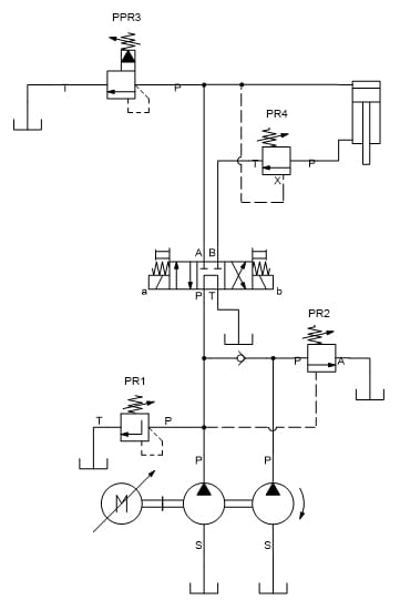
Given that and taking into account your suggestion I have changed the flow control valve by a counterbalance valve:
simplified_hydraulic_circuit_hvfmvf.jpg


This is the suggestion you have given me, am I right?
This circuit shall allow the cylinder to extend and touch the workpiece, and once the pressure start to increase the PPR3 will do it's job and limit the pressure to the value set by the controller.
However this circuit will only allow the cylinder to extend if the set pressure of PR4 is lower than the set pressure of PPR3, do you agree?

Now my question is how can I quantify/calculate the extension speed of the cylinder given a set pressure of PR4?
 
You would be better off having a pressure switch on the rod end of the cylinder. Use it to sense the pressure in the rod and when the pressure in the rod end drops off, unload the big pump.

If there is a risk of breaking the workpiece, I would suggest changing PPR3 to a proportional pressure reducer. Put a pressure sensor or gauge on the head side of the cylinder. Then, on the down stroke, the net downward force would be zero. The pressure on the head side of the cylinder being just enough to open the motion control valve. As the press touches the workpiece you will have more control of the force acting on it. You can then adjust the pressure with a current. Starting low and going high. Add a direct acting relief to protect from over pressure.

This is a more costly solution but it will be much more safe and controllable.

Cylinder velocity is flow in over the area of the cylinder.

You need a check valve on the big pump too...
 
You also need a check valve to go around the motion control valve - to lift the press
 
HPost said:
You would be better off having a pressure switch on the rod end of the cylinder. Use it to sense the pressure in the rod and when the pressure in the rod end drops off, unload the big pump.
If I unload the big pump won't the cylinder head pressure drop off?
That's why I need the check valve on the big pump, right?

HPost said:
As the press touches the workpiece you will have more control of the force acting on it. You can then adjust the pressure with a current. Starting low and going high.
I don't understand this suggestion.
If I have a proportional pressure relief valve with a set pressure of say 5 bar, and PR4 has a set pressure of say 3 bar, won't my proposed circuit lower the cylinder rod until it touches the workpiece without ever going over 5 bar, and once it touches the workpiece the rod pressure drops to 0 and the head pressure goes to the pressure set in PPR3 (5 bar)? Are you concerned that PPR3 may allow a bit more pressure to build before it opens than the set pressure of 5 bar?

HPost said:
Cylinder velocity is flow in over the area of the cylinder.
Let us assume the circuit has only one pump. Can I assume the flow to the cylinder is the same as the flow the pump provides, even though there is a counterbalance valve at the rod end of the cylinder?

HPost said:
You need a check valve on the big pump too...
The big pump that is missing a check valve is the one with the higher pressure and lower flow rate.
What could damage the pump if the check valve was not installed?
Is it just to prevent the head pressure to drop off right?

 
and if we have the rod side of the cylinder open to tank, shouldn't the net force be equal to Pa*Aa? (i.e.: shouldn't Pb = 0?)
If the rod side is always open to the tank then yes. However if you are metering out with the rod side then obviously no.

Cylinder velocity is flow in over the area of the cylinder
NO!!!!!
The press will accelerate downwards until the sum of forces acting on it are zero.

You need to consider what gravity will do to your press if the rod side is open to tank.
YES!!!! And there will be a vacuum on the top side of the cylinder.
Flow isn't required is it?

Leandro, you need a controller. You can try to do this application cheaply and waste lots of time and some money or do it right.
Do you have any idea how quickly force will increase when contact is made. It will be quite fast, possibly milliseconds. Much depends on the kinetic energy of the press when contact is made and the compliance of the vessel or.....
You need a valve with a servo quality spool. You need force feedback for sure. You need position feedback if you want to reduce cycle times.
It would also be helpful to put the vessel on something that is a little compliant so that the vessel doesn't get smashed. Cheap valves and slow controllers will not respond to pressure increases fast enough if there is no compliance.

A good hydraulic motion controller with position feedback will retract just far enough to remove and insert the vessel then approach the vessel quickly and slow down to the correct contact speed. This is the speed that builds up force quickly without going over the force limit or set point. The press coming down has kinetic energy. The contact speed should be just high enough have enough energy to do the required work on the the compliant rubber beneath the vessel unless you really want the vessel to deform. The work done is the integral of force x distance. The vessel will still have the desired force across it however it is the compliant piece that is absorbing the shock.


Peter Nachtwey
Delta Computer Systems
 
Peter likes to unload ALL of the information in one go. He is not wrong, I just prefer to overlook the fact that a vacuum will exist in the head of the cylinder and where I say cylinder velocity is Q/A - that is not wrong either. It is the steady state velocity once the cylinder has been accelerated. In reality, as the motion control will hold the press up and you will need to effectively force the press down, the acceleration will be very quick and once it is up to speed, the steady state velocity is a function of the flow into the cylinder. The flow out is a function of the volume ratio in the cylinder - head end to rod end.

Don't overlook the fact that when the press touches the workpiece, there is instantaneous change in the dynamics. The press decelerates, the flow out of the rod end stops and the pressure in the head end increases rapidly.

If there is no motion control valve, opening the control spool would allow the press to drop. As the press would approach 9.81m/s^2, the volume required to keep the head full of oil can never be achieved. The vacuum in the head side tending to zero in extreme cases, there is a net upward force. The press would bounce.

Regarding the pump unloading - I read the drawing as the bigger pump being closer to the drive motor. That is normal convention. The biggest displacement pump should always be the closest to the motor. If you don't have a check valve, the higher pressure pump will try to motor the lower pressure pump. It will add load or stall the pumps depending on the situation.

The point of unloading the big pump is to reduce the power consumption. As the press contacts the workpiece, the flow is not needed and the pressure will increase. If you don't unload the big pump, you will just dump all of the flow over the relief valve and that will waste energy. You only need pressure and that can be provided by the small pump.

My suggestion on using a proportional pressure reducer assumes that all pressures are relative to the pressure on the motion control valve.

It would work as follows:

Opening the directional control valve will open the rod end of the cylinder to tank and the pressure would start to move, but it can't, it is sat on the motion control valve.

Oil flows into the head side of the cylinder, pressure starts to build. The motion control valve being set to 10% above the static pressure in the rod end and having a pilot ratio of 2:1

Let's say that the static pressure in the rod end is 50 BAR. Then the motion control valve would be set to 55 BAR. With a 2:1 pilot ratio, the head side pressure would need to be 27.5 BAR to start the press moving. Foe Peter's benefit, yes it will be a little more than this to accelerate the press, but this is just a guide. As the motion control valve is being held open with a pilot signal, the pressure in the rod end is only from the pressure drop between the cylinder and the tank.

At the point where the press touches the workpiece, the press will decelerate and the pressure drop will decrease. The pressure in the head end will increase. You can use either one of these pressures as a signal to unload the pump. Either hydraulically or electronically.

The lowest possible pressure is the 27.5 BAR needed to move the press. You need to decide if that is too much. If it is, you need to change your pilot ratio to bring it down. I would say at this point that the pressures in the system are a function of the size of the press. If the press is too large, there will always be a risk of crushing the workpiece. What are maximum clamping forces required and how do they relate the press and what pressure is needed to generate those forces?

Assuming that the 27.5 BAR on the head of the cylinder is not enough to destroy the workpiece, this is where the pressure reducer comes in. Let's just say that the pressure reducer is high enough to move the press, but also low enough that it just grips the workpiece without damaging it - 30 BAR. Also assuming that you have identified the max pressure that you need, you can now slowly increase the pressure in the cylinder to provide the necessary force. This can also be electronic or hydraulic control. The "safety" valve being there to provide a limit to the pressure in the head of the cylinder - just in case.

Once there is sufficient pressure in the head, you can just leave it there to complete the test. Obviously the pump will be working at a higher pressure. I don't know what other work is going on with the press and the pumps, but if possible, you can turn the flow down to provide only enough flow to maintain the pressure in the head of the press cylinder, or you can leave it running at full speed.

This may well be over the top. It's up to you to decide what the end solution is. This is only some free advice on the basics...

 
Peter likes to unload ALL of the information in one go.
Not all. There are still questions.
Things became more clear with the picture.

where I say cylinder velocity is Q/A - that is not wrong either.
That in only right when the sum of forces is 0. However, V=Q/A is looking at the problem backwards. There is flow because there is motion, not the other way around and you cannot compute speed or flow using V=Q/A during acceleration or deceleration. You can not use Q to compute V because V will change as the load changes thereby affecting Q.

Now to the nitty gritty. We don't know what the cycle time is. Are all pressure vessels being tested so that testing pressure vessels quickly is important? There is a huge difference between testing one part per day and one part per minute. We don't know much the press must move to get parts in and out. I could optimize this diagram some if I knew a hydraulic motion controller was being used. For instance the speed of the motor can be controlled too. From the diagram it looks like the motor is supplying all the energy whenever motion or force is required. I always look for ways to use a smaller motor and store energy in an accumulator when the press is not moving. PR4 needs to be removed if using a hydraulic motion control. PR4 will interfere with closed loop control. Sometimes a combination of open loop for position control and closed loop for force control works best.


Peter Nachtwey
Delta Computer Systems
 
Unless there is cavitation in the oil, the equation, V=Q/A, is always true. And for a positive displacement pump, driven by a a constant speed motor, Q will be fairly constant.
 
I am sorry for the late reply.
Thank you all for your insight and suggestions.


HPost said:
The biggest displacement pump should always be the closest to the motor.
Thank you for the information. May I ask you why is that? What would be the disadvantages of having the higher pressure pump closer to the motor? Not that I need the higher pressure pump closer to the motor, I'm just trying to understand the physical phenomena that drives the decision to place the pumps.

HPost said:
What are maximum clamping forces required and how do they relate the press and what pressure is needed to generate those forces?
This testing machine will test pressure vessels from various dimensions. We need to exert from 10ton up to 120ton.
This means, with a cylinder whose piston has a diameter of 250mm, that we need to apply from 22 up to 250 bar of pressure.

HPost said:
My suggestion on using a proportional pressure reducer assumes that all pressures are relative to the pressure on the motion control valve.

It would work as follows:
...
I was thinking that conceptually the circuit I propose should work as follows:
- For all pressure vessels under test: Set PR4 pressure to 5bar (i.e.: we only set PR4 once, when the press is assembled...)​
- For all pressure vessels under test: Set PPR3 (proportional pressure relief valve) to 10bar​
- After the rod touches the pressure vessel the clamping force will increase upto: 4.9ton (less than what would deform even the smallest pressure vessel)​
- As soon as the pressure at the P side in PPR3 stabilizes: pressurize the pressure vessel up to 8bar (the reaction force it would exert on the press will be lower than the clamping force, and so it will seal against the flange that's mounted on the rod​
- Once the pressure inside the pressure vessel is 8bar, set the pressure of PPR3 to 20bar.​
- As soon as the pressure at the P side in PPR3 stabilizes: pressurize the pressure vessel up to 18bar​
- Repeat until the pressure of the pressure vessel is the pressure required for testing​

In summary: We want to apply a gradually but discrete increasing clamping force to the pressure vessel.

Can you comment on my description of the working of the press?
 
Status
Not open for further replies.

Part and Inventory Search

Sponsor