Continue to Site

Eng-Tips is the largest engineering community on the Internet

Intelligent Work Forums for Engineering Professionals

  • Congratulations KootK on being selected by the Eng-Tips community for having the most helpful posts in the forums last week. Way to Go!

Electro-Magnet drop out time

Status
Not open for further replies.

demedeirosa

Electrical
Jun 23, 2012
15
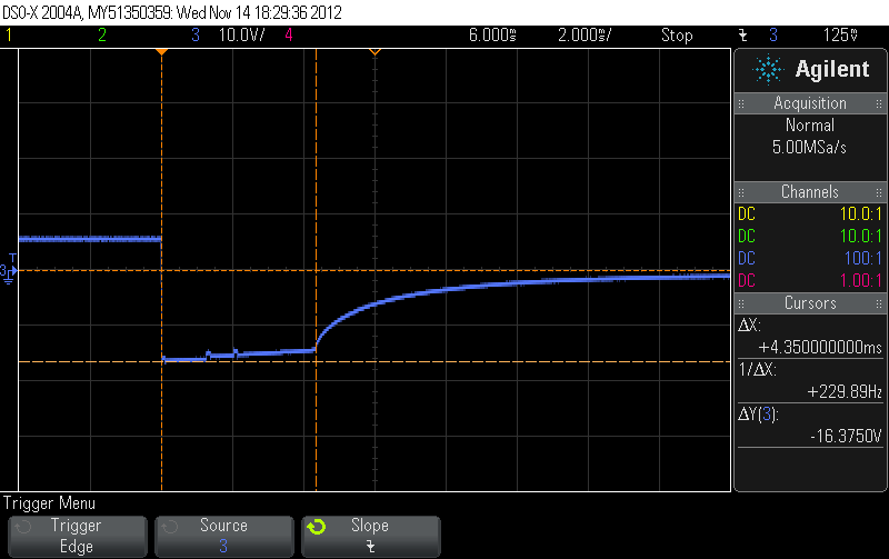
I'm trying to decrease the amount of time it takes for an electromagnet to actuate. Currently we're driving it with two MOSFET's, to drop out both sides of the magnet. The MOSFET's im using are 300V, N-CH, link below. I am familiar with the idea of letting the inductive spike peak to decrease coil drop-out times, hence the reason for going with 300V MOSFET's with a 12V magnet. I was hoping that the 300V MOSFET would not clamp, therefore allowing my spike to quickly dissipate, but in reality I am clamping at roughly 16V.

Any one have any insight?

scope_0.png


Replies continue below

Recommended for you

Could it be that it's not the MOSFETs that are "clamping" but some other parasitic conduction path around the coil? I would suspect parasitic capacitance in the wiring, except that the dV/dt during discharge is quite low. Instead, could there be insulation breakdown initiated by the high dV/dt (and perhaps hidden overshoot) at the start but then sustained as a small arc for the 4.3ms? It's just that an arc has roughly Zener-like behaviour once it is established, which is kinda like what you're seeing. 16V is about a centimetre of arc - could this be occurring, perhaps within the electromagnet itself?
 
An electromagnet is essentially an inductor, so that means that it has a time constant associated with the series resistance in the circuit.

TTFN
faq731-376
7ofakss
 
Nice and smooooooooooth. The problem dear Brutus is not in our fets but in our circuits. Looks like open gate capacitance. If I had to guess it looks like it is driven by a microprocessor where the output pin goes fron HIGH to floating. Pop up a schematic.
 
Thanks for all the replies, Im not sure we've hit on the solution yet.

LiteYear- To disprove this I decided to use a SPDT switch and drive it manually. The inductive spike I see is 800uS or so long, with an amplitude of about 350V.

IRStuff - I agree, but my experiment above has shown otherwise. Also, if this was an RC decay I dont think I would see the plateau at 16V. What do you think? The magnet is roughly 42mH.

itsmoked - That's a good idea, although I may not be able to from a fail safe stand point.

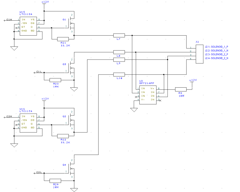
OperaHouse - The low side fet is driven by a JK flip flop (74HC109), and the high side is driven by an LTC1154 gate driver which is push pull. I will post the schematic in a few hours.

Thanks!


Here is a portion of my schematic, the signals C1H, C1L, C2H and C2L are all generated by a JK flip flop.

Circuit-1.png
 
Figured out my problem... The SP721 is a transient voltage suppressor,going against everything I want to do...
 
One obvious problem is that the high-side driver should be a p-channel to eliminate the threshold and body bias drop from the source following n-channel.


TTFN
faq731-376
7ofakss
 
IRStuff - I'm not sure i follow you completely. With the use of a gate driver why is a p-channel needed?

btrueblood - This is to prevent failure, in the case that either fet fails to drop out.
 
Gate drive = 12V
Typical 300v MOSFET threshold = 3V
Maximum possible source voltage = 9V
1A IDS required VGS = 6V --> maximum output voltage = 6V

This is freshman EE stuff here.

TTFN
faq731-376
7ofakss
 
What would cause the FET to fail? Use a higher-rated FET?

Not sure why you chose the SP721 to snub the magnet coils. I'd put something more mundane, like an opposed Zener pair, or Zener and standard diode if only switching one side. That at least gives you flexibility to pick the zener voltage as high as you are comfortable with, and speed the coil decay time.
 
IRStuff - I am following what you say, but my gate drive is not 12V. It is roughly 30V, the LTC1154 is a charge pump driver.

I apologize for my lack of knowledge on the subject. Its been a long time since freshman year, especially when not designing mosfet circuits on a regular basis.
 
Status
Not open for further replies.

Part and Inventory Search

Sponsor