Continue to Site

Eng-Tips is the largest engineering community on the Internet

Intelligent Work Forums for Engineering Professionals

  • Congratulations KootK on being selected by the Eng-Tips community for having the most helpful posts in the forums last week. Way to Go!

Excessive Pump Nozzle Load - Suggestions to reduce it? 6

Status
Not open for further replies.

Gears6580

Mechanical
May 5, 2024
8
Hello All,

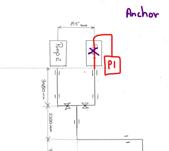
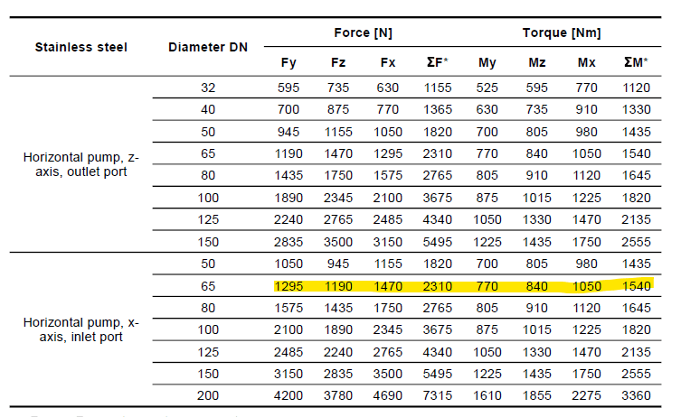
I am new to pipe engineering, and I am trying to do pipe stress analysis to learn the software(Autopipe). I would like to get your opinion on routing the followng pipe based on your experience to reduce the nozzle load on the centrifugal pumps. I would also appreciate if you could point me out to good resource for pipe engineering best practices.

Info:
Medium - Water
Ambient temp - 15 C
Temperature - 95 C
Material - A312- TP316L Stainless steel schedule 10
Pipe Size - DN150
Pump Suction - DN65


Constraints -
Pumps and tank cannot be moved
Height of the pipe cannot be altered, any expansion loop must be horizontal
Pumps may run in any configuration i.e. they can run simultaneously or may work on single pump(either or)
Prefer not to use expansion bellows

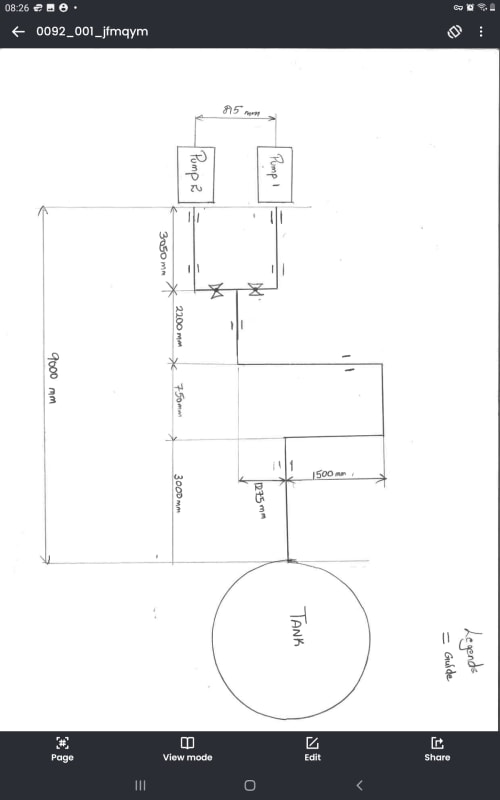
Layout drawing attached. Any help/advice would be appreciated.

Thanks.
Screenshot_2024-05-06_134455_yg9vyl.png

Screenshot_2024-05-06_134534_jtsiee.png

[URL unfurl="true"]https://res.cloudinary.com/engineering-com/image/upload/v1714961534/tips/0092_001_jfmqym.pdf[/url]
 
Replies continue below

Recommended for you

Screenshot_20240506-082628_PDF_Reader_-_Hi_Read_xdjlrd.jpg


Pressure is?

You don't leave us a lot of options.
Remove the guide on the loop.
Remove other unnecessary guides. Replace them with vertical supports.
Extend the loop. 1500mm is nothing. Probably needs 5m.
Widen the loop. 750mm is nothing. Probably needs 3m min.
Keep on extending the 1500mm dimension until it works.
Add another loop if needed.

--Einstein gave the same test to students every year. When asked why he would do something like that, "Because the answers had changed."
 
The pressure is 4 bar.

The problem is when only one of the pump is working, the temperature difference in pump 1 line (15 C) and pump 2 line (95 C) causes opposing loads on the pump nozzle.

thank you for your advice.
 
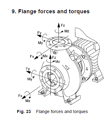
The problem with this is often that the program treats the pump nozzles as absolutely rigid points with zero flex when in reality they do. Thus even 5 microns of expansion turns into a huge force or moment. Reality is that this flexibility is there so the forces are not what you see.

I would put an anchor or line stop as close to the pump nozzle and the tank nozzle as you can and let the pipe flex. Model the flanges as free ends so you dont get unrealistic forces between the anchor and the pump nozzle due to some very small expansion.

Temperature increase of 80 C is quite high to accommodate on such a small system without bellows or flexible connections.

Remember - More details = better answers
Also: If you get a response it's polite to respond to it.
 
Thank you. You are right, the nozzle has been modeled as rigid and thus any small expansion creates massive loads. I assume the pump manufacturers can provide the detail for allowable displacement? I can place anchors close to the nozzles and model the nozzles as free ends which will give me max nozzle displacements. If not can you please let me know of any source where I can find the allowable nozzle displacements?

Placing the bellows in front of pump causes pressure thrust but this is within acceptable limits and solves the problem but because bellows have low fatigue life I'm trying to eliminate them.
 
Pump vendors won't tell you anything, but I would use 1 or 2 mm as gasket compression or indeed pump flex.

Or maybe extend the pump discharge piping and have it as two branches off that pipe that goes at right angles? The minor difference between the two pumps won't be seen if you only run one at a time.

Remember - More details = better answers
Also: If you get a response it's polite to respond to it.
 
I usually use Caesar II which is a different program, but in that I model the pump body from nozzle connection to pump anchor as rigids (non-pipe members that don't have allowable stresses) and connect it to the piping at the nozzle, which captures the growth of the pump. Normally this growth for a hot pump is away from the pump anchors (expansion) so it actually hurts you a little nit more.

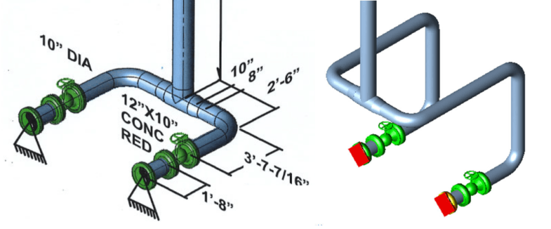
If your loads are still high, you have to reroute the pipe to add flexibility. Something like below is not at all uncommon in hot services in my experience. Alternatively you could add in expansion joints, but those are wear/maintenance items that some clients don't allow.
pump_gau9gq.png
 
Suction lines of pumps can be difficult stress-wise since they can be long lines before they get to the pump and they must be maintained horizontal. What I have frequently seen others do and have done myself, when I had no other choice, is to install removable dummy leg anchors welded to the suction lines about 1.5 ft away from the pump nozzles, or as close as you can get. This will absorb any load on the pump nozzles. The distance to the pumps will be so short that any thermal expansion of the short pipe length between the anchor and the pump will not effect the pump alignment. For your case at 133 F delta T and 1.5 feet with carbon steel piipe the thermal expansion between dummy leg and pump is 0.014". The pump should have enough flexibilty to take this.

However when modeled in the program you would stop at the dummy leg anchor since if you model the pump nozzle with dummy leg anchor 1.5 ft away you will get enormous ficticious loads predicted by the program since you would have a fully restrained pipe.
 
Snickster says ot better than me, but same advice.

Remember - More details = better answers
Also: If you get a response it's polite to respond to it.
 
Snickster,

Do you have sketch/diagram of that layout? I think I get the approach but to me that seems like it's going against the goal of the pipe stress - reducing loads on the pump. Sure, the pump nozzle is growing into the piping maybe 1/16" and that short section of pipe between the anchor and pump is growing into the pump a small value, and neither pump nor anchor are perfect ideal anchors, but those two values will fight each other and easily impart a load that could exceed the low allowable loads pump manufacturer's provide.
 
The point is that that 1/16" is taken by the gasket it by very small flex of the pump. When it moves the force disappears. A bolted flame joint has afair bit of flexibility compared to a welded connection. This is where you need to get realistic and not believe everything the analysis tells you because it doesn't model flexibility very well.

Remember - More details = better answers
Also: If you get a response it's polite to respond to it.
 
I get that approach, I would've just expected something like that to show up in Peng's or in the 3-Day Stress Analysis training course, or some other source, if it was reliable. Otherwise it feels like doing the analysis and then stopping at the important part (the nozzle) because suddenly the program is not realistic.
 
Here is a project I worked on a while back for ExxonMobil SYU Hondo in California with details of anchor at pump. The dummy leg can be seen in the upper right most Section C of the drawing P-7601 with P-7631 which is an anchor attached to a structural steel skid. Also included is standard Brown and Root pipe support details for this support.
 
 https://files.engineering.com/getfile.aspx?folder=21568c1f-0d2e-45c1-a69b-f0914b4e79d2&file=Anchor_at_Pump_Suction.docx
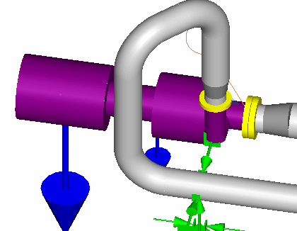
My go to solution for pump loads is to loop the piping back to an anchor close to the pump mounts.

Screenshot_2024-05-07_121014_c0rl4z.png
 
@Snickster- Great resources and examples, thank you for sharing. Additionally I was able to understand the reasoning for allowable 0.016 in displacement from API 610, Annex F. Correct me if I am wrong, I believe as long the displacement (expansion due to pipe + pump casing/nozzle) is <0.016 inch (which can be achieved by placing a stiff anchor in front of the pump nozzle) the design would be acceptable?

Screenshot_2024-05-07_165233_qkpza4.png


@KevinNZ - Great technique for discharge lines, would you do the same 180 deg loop for suction line as well?

Screenshot_2024-05-07_170938_paq4qb.png
 
"0.01 inches": A magic number that converts impossible physics problem into engineering solution.

--Einstein gave the same test to students every year. When asked why he would do something like that, "Because the answers had changed."
 
Thanks Snickster, very interesting articles and it's frustrating that the low allowable load from vendor situation persists 20-30 years later (and seems to have generally gotten worse in my experience).
 
Status
Not open for further replies.

Part and Inventory Search

Sponsor