Continue to Site

Eng-Tips is the largest engineering community on the Internet

Intelligent Work Forums for Engineering Professionals

  • Congratulations IDS on being selected by the Eng-Tips community for having the most helpful posts in the forums last week. Way to Go!

Fan motor with a VFD running at low frequency question 10

Status
Not open for further replies.

Coco_HueHueHue

Electrical
Apr 8, 2018
49
Hello,

I did browse the internet a lot and only found part of the answer to a question i am asking myself.

I keep reading that running a VFD in V/Hz control mode at a low frequency will overheat the motor.
I keep reading that the magnetizing current is significant and the motor can't cool down because of its slow rotation (internal fan).

Honestly, i do not understand why the motor would overheat at a low frequency... we have a constant V/Hz ratio.
If the frequency is 0 or very low, then, the voltage will be 0 or very low.

How can a motor overheat when almost no voltage is at its terminals?
I understand that there is no cooling, but if the voltage is near 0... the current has to be near 0 too...

If a motor nominal current is 20 Amp at 600VAC/60Hz, then, at 0.5V/0.5Hz, the current should be 16mA... maybe a little more because of the magnetizing current. But the magnetizing current is constant (from the motor design) and is very small compared to the load current.

I believe there is a piece of information i am missing.

I AM NOT SEARCHING FOR A ANSWER LIKE : "WHEN YOU RUN A MOTOR AT LOW SPEED IT OVERHEATS".
I browsed google a lot and this is the only thing i found.

Does anyone have a clear explanation, a technical article or a good book reference explaining this?
Thank you very much!
 
Replies continue below

Recommended for you

LH, I don't believe he ever said he was going to run it at 60Hz all the time. In fact his question was ABOUT running it at low speeds.

But your other point is a good one, that with a centrifugal load like a fan, at some low speed the fan not longer moves enough air to be able to overcome static pressure so although there is almost no load on the motor making it unlikely to overload or over heat, it's also pointless to run it at all because it is serving no purpose either.


" We are all here on earth to help others; what on earth the others are here for I don't know." -- W. H. Auden
 
Thank you all.
The discussion is very useful.

Indeed jraef, my question was more to understand what happens and what is implied when running a motor at low speed than actually using it at low speed. I wanted to understand how to properly protect the motor and what conditions were dangerous for the motor.

This whole discussion has been greatly appreciated.
 
Still waiting for the data from greybr. & Sofist...

Gunnar Englund
--------------------------------------
Half full - Half empty? I don't mind. It's what in it that counts.
 
Yes, running at 60Hz was posted.

8 Apr 18 16:55 - "As a matter of facts, for our appilcation, i could set the minimum frequency at 60Hz since its the only speed i have interest in."

I was just asking, why use a VFD on a constant speed application and add about 5% to the losses of the system?
 
Only because I do the commissioning of the system and it is not me who designed it nor wrote the performance requirements of the project :)
 
Ah, missed that.

Coco_Eng,
If you are concerned about protection and very low speeds, it's common for people to use embedded thermistors (or RTDs) in the motor as an added feedback of actual stator temperature. Most VFDs have the ability to accept a thermistor input from the motor as one of the inputs to the drive and use that to supplement the OL protection scheme, some can also accept RTDs or have an accessory card that will accept them. In fact if the motor is rated for classified (Ex) areas, it is a requirement in may jurisdictions. The thing is though, the motor must have the thermistors (or RTDs) embedded in it already.


" We are all here on earth to help others; what on earth the others are here for I don't know." -- W. H. Auden
 
Hi Coco_Eng,
in attachnment some measuraments made on a ABB/Schnider/(other don't remember name) VFD with 2 type of filter (to motor and to line).
The measurements made on a cable to motor.
At the end you can see comparison of signal with inverter and without (but in this case there was a 3th harmonics high so i compared a VFD output respect to sinusoidal with one Harmonic).

Hoping to give you some help

Regards
 
 https://files.engineering.com/getfile.aspx?folder=8bd53f15-b069-4916-8cb2-aca6db47a707&file=Inverter_measurements.pdf
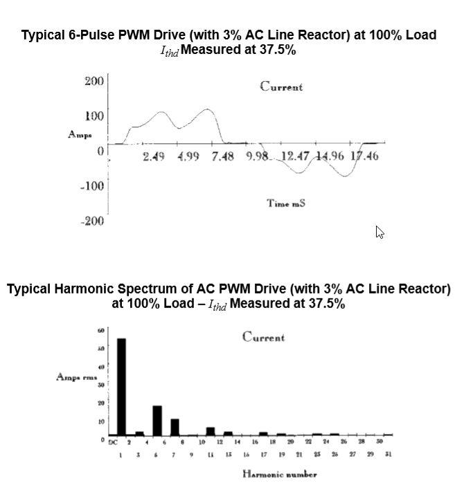
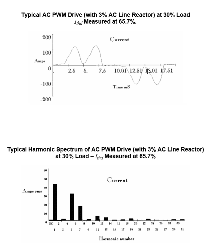
Skogsgurra asked if I had any waveforms - now attached
Waveshapes_100_load_ie4npc.png
Waveshapes_30_load_deubmn.png
 
graybrookie - You're showing the harmonics on the input to the VFD, not the harmonics going to the motor. The 5th and 7th input harmonic current levels rising as the load is reduced is rather odd.
 
LioneHutz. The illustration shows the harmonics generated by the VFD in the creation of the PWM waveform controlling the motor speed. The increase in harmonic current as the load reduces, maybe not what you would expect, but is exactly what happens in practice. The illustration was taken from a live recording.
 
Yes, Greyb. That is right - apart from not being the motor current, which the discussion is about. The reason that THDi increases with reduced load is that the peak rectification that charges the DC link capacitors takes less time (smaller conduction angle) the less current you draw from it. Shorter current pulses means more harmonics. A simple and well known fact. But, the discussion here is about motor heating and speed and that is where Sofist's recordings comes in.

Let's study the example with the lowest load. The one where fundamental voltage is 255 V:
The first comment is that it is not percentage that heats the motor - it is actual current. In amperes.
Second, there are no even harmonics in the output of a VFD. Only odd ones, like third, fifth, seventh etcetera. The recordings show lots of even harmonics - dominating, actually. The reason for this is explained below.
Third,the "plausible" harmonics (third, fifth, seventh etcetera) make up less than 5% of the total current. That means that they would contribute with less than one quarter percent of the heating. Which wouldn't worry me the least.

So, why are there so high levels of even harmonics in the analysis? The answer is that there are lots of interference from the PWM edges and that the PQ instrument (looks like a Dranetz) cannot handle those high frequencis (to low sample rate) and that it doesn't have an adequate anti-alias filter built in.

In such cases, it tries to interpret the input signal the best it can and, since the frequencies above the Nyquist frequency are fold back to the frequency range it is designed to handle - aka aliasing - it sums all the energies it can see, including the alias frequencies, and puts them in the available harmonics bins. That is how you get a lot of the non-existing even harmonics and also a fair share of extra odd harmonics.

If you do the measurements with carefully protected signal paths and an LP filter (single pole usually works very well) with f0 at around 3 kHz, you will get an antirely different result. And much closer to reality.

Gunnar Englund
--------------------------------------
Half full - Half empty? I don't mind. It's what in it that counts.
 
Well, considering how little it appears your waveforms change in your recordings, I don't believe they are accurate.

I just went back and looked at some recordings I made with a 3% reactor. When the load dropped from 100% to 30%, the current peaks dropped from about 100A to 55A. So, I find it very hard to believe that your readings with the the current peaks increasing when going from 100% load to 30% load on the motor are accurate. It appears the peaks in your waveforms actually increase as the load is reduced, which simply makes no sense.

Anyways, this has nothing to do with the harmonics reaching the motor and are not indicative of any extra heating effects in the motor.
 
Gunner - I hadn't commented on the data from Sofistioelevib, but it did appear to be data from a typical power quality analyser, and from what I have seen I'd agree that most of them are not suitable to use on the output of a VFD and therefore can't be expected to be trustworthy.
 
Yes, Lionel. It has always been like that. They are PQ instruments and not motor analyzers. Their CMRR is terrible and I usually disconnect the voltage paths and put brass foil with ground straps between Cable and current clamps. That way, you can use a Drantz - sometimes.

Gunnar Englund
--------------------------------------
Half full - Half empty? I don't mind. It's what in it that counts.
 
Status
Not open for further replies.

Part and Inventory Search

Sponsor