Continue to Site

Eng-Tips is the largest engineering community on the Internet

Intelligent Work Forums for Engineering Professionals

  • Congratulations IDS on being selected by the Eng-Tips community for having the most helpful posts in the forums last week. Way to Go!

Feature Of Size definition

Status
Not open for further replies.

Sem_D220

Mechanical
Jul 9, 2018
290
My first question is - according to ASME Y14.5 2009, how would you classify the cylindrical interrupted surface of diameter 55 and the width 52 in the following sketch?
Are they:
- Regular features of size (with interruptions)?
- Irregular features of size type A? (Or maybe even B?)
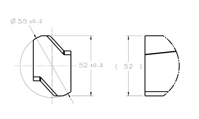
FOS_QUESTION_aejzhn.jpg


My second question is for those who have access to the 2018 standard:
What is the change that was introduced to the concept of feature of size?
I read that there was a change in the concept in the announcement at the ASME website which pmarc linked to in the thread about the new standard.
 
Replies continue below

Recommended for you

pylfrm said:
I think the candidate datum set definition would apply in all cases where a tangent plane is required (including Fig. 6-18) because para. 2.16 (tangent planes) refers to para. 4.11.2 (datum features) which refers to the Y14.5.1M definition.


What do you think the UAME should be for the feature with coordinates posted 28 Mar 19 01:57?

Paragraph 2.16 says: "If the tangent plane is unstable it may be optimized. See para. 4.11.2 and ASME Y14.5."
It doesn't require optimization in every single case. So unless there is an instability situation for the 0.80 envelope for the feature with coordinates posted 28 Mar 19 01:57, I wouldn't require candidate datum set validation, and say that envelope 0.80 is the UAME envelope.

pylfrm said:
Consider a different case: determination of the maximum inscribed sphere for a set of points. There will always be four contact points, but that's just a consequence of the geometry. It would not make sense for the definition of the UAME of an internal spherical surface to explicitly require four contact points

I'm not sure about that. Let's start with a simpler case of a 2D maximum inscribed circle for a given set of points in 2D. Unless there are 3 points located on a perfect radius, which is not likely, the maximum inscribed circle will have to pass through 2 points. If it passes only through 1 point, it is not really the maximum inscribed circle. So here we see that the number of "contact" points is meaningful.
 
pylfrm 29 Mar 19 00:23 said:
I disagree. That is the unique envelope of minimum width, so rocking would not be possible without an expansion of the envelope. Earlier examples behaved differently due to greater curvature of the surfaces.

This is another point I wanted to address and I finally got to it now - according to my check, rocking of +-1° of the envelope planes around the two radii on the opposed faces would produce an increase of the envelope by as little as 0.013mm (from 20 to 20.013). So from a purely theoretical aspect, your assertion is correct - it is impossible for the envelope to rock without enlarging, but practically I doubt the ability to determine an envelope that behaves this way repeatably.

If we were to simulate a datum center plane from this feature, if I may return for a minute to the notorious requirement in para. 4.11.4 for the undefined "maximum possible contact", then despite the lack of a definition, it is obvious that the envelope of size 20.026 makes more contact with the feature than the 20 envelope. So, which would be the more valid UAME envelope for a primary datum center plane simulation?
Should we ignore a requirement specified in the standard just because it uses a term not defined well enough?

Edit: the subject of this post is the figure posted by chez311 at 27 Mar 19 15:22.
 
it is obvious that the envelope of size 20.026 makes more contact with the feature than the 20 envelope.

Is it really?

Imagine we measure a bunch of points on this feature with a CMM (with some small random measurement error), and then find the minimum-width envelope of those points (in 2D). Perhaps 19.999 is the result. This envelope will contact two measured points from one surface, and one measured point from the other surface.

Now imagine we rotate the envelope through a range of approximately +/- 5 degrees from the minimum width. We'll have a close approximation to the theoretical 20.026 envelope at somewhere around 1.43 degrees of rotation. Over the entire 10 degree range, the envelope will almost always contact only two measured points. Occasionally it will contact three points, but not more.


pylfrm
 
Sem,

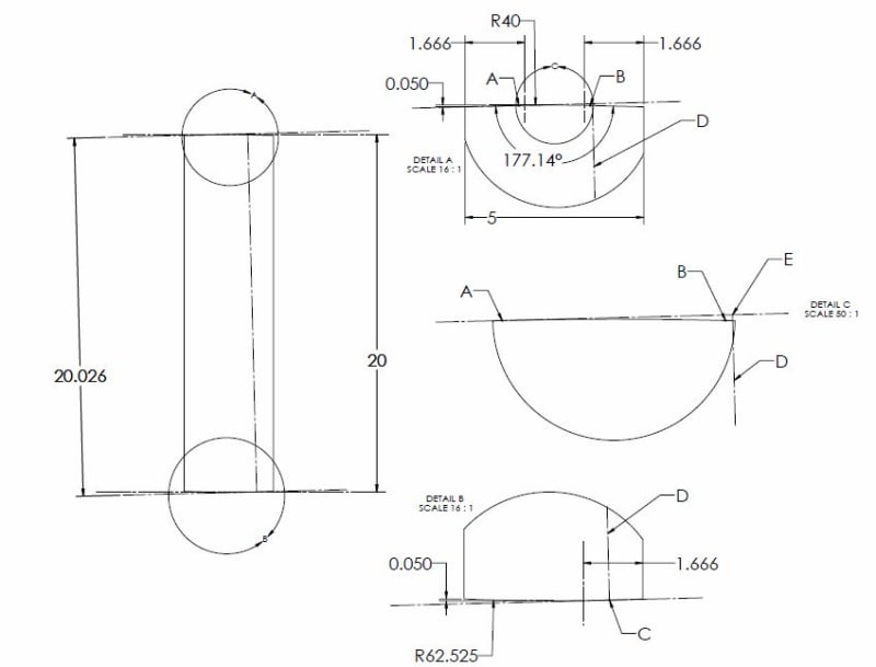
See my figure below. While I also think that a convex surface like this with small amount of form error will have issues with repeatably physically simulating that minimum 20 boundary, I do not think that the additional requirement for contact which you have stipulated (resulting in the 20.026 boundary) imparts any increase in stability. So long as we are discussing the physical realities of inspection/simulation - as your boundary rotates, in addition to increasing in size as pylfrm mentioned (however infinitesimally), the line which is normal to the planar boundary on each side (this envelope being tangent to the convex feature surface) increases in separation from the contact points of the boundary on the opposing side. This is represented in my figure by line D, intersecting with the convex surface (of R62.525) and the planar boundary at point C, which intersects with the opposing boundary at point E. Since the closest contact point on the opposing surface is at point A, I would think that the part/boundary would want to pivot around this point towards the minimum envelope as the boundary contracts since the physical reality would be that the simulator would exert a force on the surface creating a moment about this point.

That being said, I do agree that there would be issues with repeatably simulating the theoretical minimum of 20, as there might be with any convex feature - hence the need for a stabilization procedure through the candidate datum concept. In reality I think I would expect the result to be somewhere between 20.026 and 20, the point being though that the "increased" contact at 20.026 does not in my opinion result in any more stable an envelope (or make it any easier for the operator to find the elusive point of "maximum contact") and during simulation I think you would find that the resulting simulated envelope would be biased toward the minimum 20 envelope.

Finally, I rechecked the figure after pylfrm's notes about candidate datums/tangent planes and it just so happens that the points A and B where the planar portions of the upper surface meets the convex portion lie within 1/3 of the width from either end of the feature. Unless I am missing some nuance of the concept, I do not believe the boundary on either side of the 20.026 envelope would be valid tangent planes.

FOS3C_l67iqr.jpg
 
pylfrm, If we are talking 2D,
The 20 (or 19.999) envelope should contact one point at one side and one point at the opposite side - those are the apexes of the two radii in chez311's figure.

At 1.43° of rotation, as you say, is the approximate 20.026 envelope where theoretically the top plane of the simulator lies flat on the flat section of the top face. In practice, this is equivalent to 2 contact points at 2D.

In 3D, I don't think it would be hard to find an orientation where the top plane contacts the flat section of the top face at 3 points. Then the other plane parallel to it will contact the bottom arc-shaped face at 1 point. For the approximate 20 envelope, this amount of contact is not guaranteed.
 
chez311 said:
Since the closest contact point on the opposing surface is at point A, I would think that the part/boundary would want to pivot around this point towards the minimum envelope as the boundary contracts since the physical reality would be that the simulator would exert a force on the surface creating a moment about this point.

chez311, that is true for physical gauging simulation, and for physical gauging, both envelopes would have stability issues (the 20 as you agreed, and the 20.026 as you just rightfully pointed out).
If the simulation is done with CMM and an appropriate computer program, there's a substantial possibility to find an orientation that conforms to the "maximum possible contact"/"contact on the high points"/"tangent plane" (choose the least-worse wording) condition at one of the 2 orientations corresponding to the approximate 20.026 envelope, because this is where a plane contacts a more or less flat portion of a surface. This still doesn't lead to a single solution as there are going to be 2 of them, but it doesn't ignore the required amount of contact implied by the definitions in the standard.

In addition, I am not sure that the candidate datum set concept must be applied in this case. It probably must be for physical simulation - with that I agree.
 
Sem,

I don't think I ever said the minimum 20 envelope had stability issues - I said I agreed it may be difficult to simulate repeatably. I would say it is the most stable envelope that could be derived from the feature as shown.

Sem D220 2 Apr 19 16:31 said:
In addition, I am not sure that the candidate datum set concept must be applied in this case

Thinking about it, it seems to me that the candidate datum set concept is probably always in effect. Its just whether that datum set consists of no solution, a single stable solution, or multiple solutions. I don't think you can have a solution/tangent plane/candidate datum plane which is valid for a given feature/surface but not a valid candidate datum.
 
chez311 said:
I don't think I ever said the minimum 20 envelope had stability issues - I said I agreed it may be difficult to simulate repeatably. I would say it is the most stable envelope that could be derived from the feature as shown.

My bad. It doesn't necessarily have stability issues, but it does have repeatability issues, as you agreed. I acknowledge the difference, even though often repeatability of measurements/simulations is tightly related to stability. Whether or not a case of some additional form error (probably inevitable in reality) will cause the considered feature to become unstable in interaction with the size 20 envelope - probably better not to get into it.

chez311 said:
Thinking about it, it seems to me that the candidate datum set concept is probably always in effect. Its just whether that datum set consists of no solution, a single stable solution, or multiple solutions. I don't think you can have a solution/tangent plane/candidate datum plane which is valid for a given feature/surface but not a valid candidate datum.

Y14.5 only refers us to candidate datum set where rocking issues are encountered. More specifically where the as produced geometry of a planar datum feature or a surface for which a tangent plane is required cause the instability of a physical datum feature simulator. What prescribes the application of the candidate datum set for the following cases?
1. Computerized datum/tangent plane simulation for a scanned feature where physical stability does not come into play.
2. Even more importantly - physically stable envelopes where all projected contact points fall within the near-edge 1/3 of the length of a line along the candidate datum plane, such as in the case of the feature described with coordinates by pylfrm at 28 Mar 19 01:57.
 
Sem D220 2 Apr 19 20:07 said:
What prescribes the application of the candidate datum set for the following cases?

Y14.5.1 governs the mathematical definition of many of the concepts in Y14.5 and is the basis for CMM measurement/software. The fact that it is only referenced 2x in the body of Y14.5 in conjunction with rocking of datum features and 1x in conjunction with circularity does not mean it should only be applied in those cases. I would say as I said before, the candidate datum set contains every solution of candidate datums for a given feature/surface, not just ones which qualify as "unstable" or "rocking" - this can be either 0,1,or greater than 1. This is actually alluded to in Y14.5.1 and "rocking" is only mentioned as a case where there is more than one solution, even a perfectly flat surface* has a candidate datum set - it just so happens that this set contains a singular solution.

Y14.5.1-1994 said:
4.3.2 Planar Datum Features. The candidate datum set for a nominally flat datum feature is defined in a procedural manner. This empirical defintion specifies a set of datums which are reasonable from a functional standpoint. If the datum feature is perfectly flat, the candidate datum set consists of only one datum; otherwise it may consist of more than one datum. This is equivalent to “rocking” the datum feature on a perfect surface plate

*Edit - missed a word
 
If we are talking 2D,
The 20 (or 19.999) envelope should contact one point at one side and one point at the opposite side - those are the apexes of the two radii in chez311's figure.

This would be true of smooth curves, but not sets of points like I described. If you have an envelope with one contact point on each boundary and those points are directly opposed, then rotation in either direction will allow the envelope width to decrease. If the two contact points are slightly offset, then rotation in whichever direction increases that offset will allow the envelope width to decrease further.

At 1.43° of rotation, as you say, is the approximate 20.026 envelope where theoretically the top plane of the simulator lies flat on the flat section of the top face. In practice, this is equivalent to 2 contact points at 2D.

Yes, just like we had with the 19.999 envelope. The points might be farther apart, but the count is the same.

Essentially the same arguments apply in 3D. The minimum-width envelope will have four total contact points (3+1 or 2+2), and an envelope oriented differently won't have any more than that.


pylfrm
 
pylfrm, intuitively it seems that the more or less flat portion of the surface is more likely to allow tangent plane or "maximum possible contact" simulation, but perhaps you are right. Anyway, I agree with you and chez311 that the definition in Y14.5 for the required amount of contact between the feature and the simulator during UAME simulation is missing, or vague at best.

I suppose that the foregone conclusion from this discussion is that offset-opposed surfaces are better not to be treated as features of size.

Thank you chez311, pylfrm, pmarc, Kedu, axym and the others for the great input.
 
Status
Not open for further replies.

Part and Inventory Search

Sponsor