Continue to Site

Eng-Tips is the largest engineering community on the Internet

Intelligent Work Forums for Engineering Professionals

  • Congratulations cowski on being selected by the Eng-Tips community for having the most helpful posts in the forums last week. Way to Go!

Feature Of Size definition

Status
Not open for further replies.

Sem_D220

Mechanical
Jul 9, 2018
290
My first question is - according to ASME Y14.5 2009, how would you classify the cylindrical interrupted surface of diameter 55 and the width 52 in the following sketch?
Are they:
- Regular features of size (with interruptions)?
- Irregular features of size type A? (Or maybe even B?)
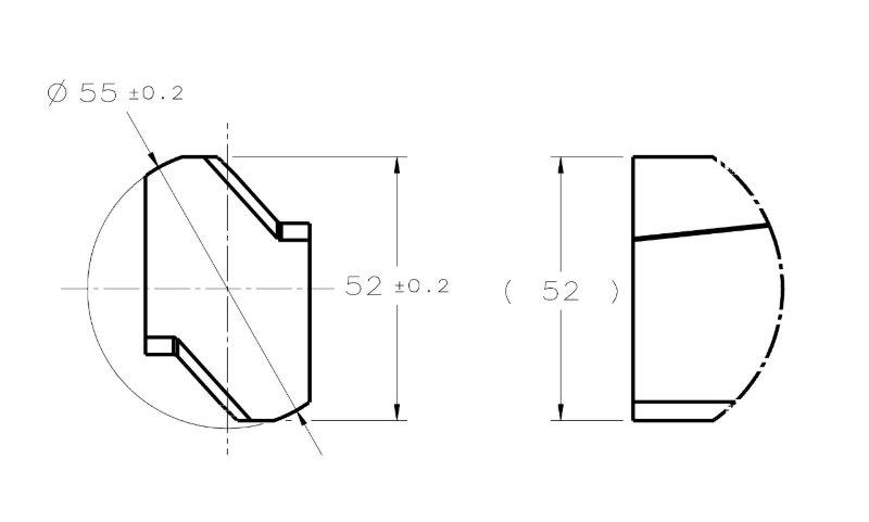
FOS_QUESTION_aejzhn.jpg


My second question is for those who have access to the 2018 standard:
What is the change that was introduced to the concept of feature of size?
I read that there was a change in the concept in the announcement at the ASME website which pmarc linked to in the thread about the new standard.
 
Replies continue below

Recommended for you

pylfrm,
For me, coincidence with the highest points means tangent adjustment between a surface and a plane (edit: or between a surface/feature and an envelope that is of the inverse geometrical form of the surface/feature).

For a planar surface, it is what required when a tangent plane modifier is specified, as depicted in fig. 6-18 in Y14.5-2009.

For a cylindrical feature, fig. 4-11 and 4-12 are probably the best references. Even though they describe datum simulation process, this is essentially a simulation of the UAME.

For a width feature of size consisted of opposed or offset-opposed faces, I think that one of the 2 parallel planes of the simulator should act as a tangent plane to its surface and the other may contact the opposed or offset opposed surface at one point. The smallest (or largest for an internal feature) envelope that can be simulated that way - is the UAME. It is possible that this description is not accurate, or you can find some fault in it. In that case, you can refer to the pmarc's idea that there should be 3 points of contact - 2 on one face and 1 in the other face. The smallest envelope that conforms to this condition is the UAME.
 
Sem D220 21 Mar 19 03:48 said:
This essentially means that if an envelope that conforms to this condition can be found for a given as produced feature, this envelope is the UAME. If the envelope can contract further, but the further contraction is accompanied by loosening the contact with the feature, the envelope that was already established when there was a sufficient contact is still valid, as it remains the smallest envelope that conforms to the definition.

Sem D220 21 Mar 19 03:48 said:
For a width feature of size consisted of opposed or offset-opposed faces, I think that one of the 2 parallel planes of the simulator should act as a tangent plane to its surface and the other may contact the opposed or offset opposed surface at one point. The smallest (or largest for an internal feature) envelope that can be simulated that way - is the UAME. It is possible that this description is not accurate, or you can find some fault in it. In that case, you can refer to the pmarc's idea that there should be 3 points of contact - 2 on one face and 1 in the other face. The smallest envelope that conforms to this condition is the UAME.

I have no issue with the concept of requiring three points of contact, I draw issue with it though when that takes precedence "where a local minima can't be detected" as you noted. Even if we were for a moment to take this as the case - the added requirements to what was initially a very simple definition (simulator progresses to its max/min size until it stops) - which I would think already works in the vast majority of cases - to allow a solution in a handful of extreme/minority cases, which could be possibly better served by a different control (ie: profile of offset-opposed planar surfaces) instead of making the definition fit them. Even still, your definition provides no way to handle the convex case, either of the opposed or non-opposed surfaces, which both have the same amount of contact no matter the size of the simulator. I am sure with some effort one could also find other similar cases such as situations where it would be bi-stable with the same boundary size with identical (3 points) contact.

Sem D220 20 Mar 19 20:33 said:
Inspection-wise, it is all a question of the available technology. If detection of the UAME which "coincides with the highest points" (according to pmarc, there should be 3 of them) is possible for a pair of "offset-opposed" surfaces, and nothing in the process contradicts the standard, why forbid it?
You previously said that you are always thinking of the fixture and inspection process. Consider then a fixture for a primary datum feature of the type in your OP having offset-opposed planar features referenced RMB. Would you say that would make for consistent, reliable primary datum feature able to constrain the required translation/rotation DOF dictated by a centerplane datum? Perhaps in the digital world with a CMM yes but I do not believe it would make a reliable fixture/gauge - especially if there was a case similar to your post 17 Mar 19 10:11 but with offset-opposed planar features, reliably simulating that second minimum with "maximum possible contact" I think would be difficult at best.

Sem D220 20 Mar 19 20:33 said:
There is nothing in the definition that says that it is mandatory that the physical contact between the feature and a simulator constrains the simulator as in a simple case of a vise that is stopped by the object it closes on.
Actually right there in the section which you referenced about RMB primary datum features (4.11.4) to include a requirement for "maximum possible contact" there is a reference to just this. It states "As a practical example, a machine element that is variable (such as a chuck, mandrel, vise, or centering device) is used to simulate a datum feature simulator of the feature and to establish the simulated datum." While not a "mandatory requirement" I would say it shows pretty clearly that the physical realities of simulation were in the forefront of the committee's mind when this was written and that "the physical contact between the feature and a simulator constrains the simulator as in a simple case of a vise that is stopped by the object it closes on" as you state was exactly what was being considered.
 
chez311 said:
the added requirements to what was initially a very simple definition (simulator progresses to its max/min size until it stops) - which I would think already works in the vast majority of cases - to allow a solution in a handful of extreme/minority cases, which could be possibly better served by a different control (ie: profile of offset-opposed planar surfaces) instead of making the definition fit them.

The way you put it suggests that I was proposing altering the definition or proposing a definition of my own. Actually, I am basing my interpretation purely on the wording of the standard. As it seems, the concept of *(that the UAME simulation must be based on) "simulator progresses to its max/min size until it stops" is merely a common convention.

An example where position would be a better control than profile is where it is only desired to control a feature of the relevant type for location and orientation, without the form requirement imposed by profile. I did not change the UAME definition to make it fit offset-opposed features.

chez311 said:
Even still, your definition provides no way to handle the convex case, either of the opposed or non-opposed surfaces, which both have the same amount of contact no matter the size of the simulator. I am sure with some effort one could also find other similar cases such as situations where it would be bi-stable with the same boundary size with identical (3 points) contact.

I did not pretend to offer a solution for any ambiguous cases. I am proposing an interpretation of the feature of size and unrelated actual mating envelope concepts based on the existing definitions in Y14.5-2009. The examples of ambiguous cases were brought with the purpose of communicating the point that the convention that only "classic-opposed" features are features of size doesn't really help to eliminate ambiguity.

chez311 said:
You previously said that you are always thinking of the fixture and inspection process. Consider then a fixture for a primary datum feature of the type in your OP having offset-opposed planar features referenced RMB. Would you say that would make for consistent, reliable primary datum feature able to constrain the required translation/rotation DOF dictated by a centerplane datum?

It would be up to the designer to decide if an "offset-opposed" feature is reliable enough to be chosen as a primary datum feature. The decision should also be according to the function of the feature in its intended application. The standard doesn't specify that only features that are reliable enough and appropriate to be chosen as primary datum features can be classified as features of size.
Furthermore, I can imagine cases where features of the same type, with larger surface area and perhaps different height to width proportions, can be supported and constrained by mating parts in assembly and can be legitimate datum features.

The practical examples of physical datum feature simulators in para. 4.11.4 are just that - examples. There are numerous references in the standard to digital simulation processes. A quick search for an example provides a portion of para. 4-7:

"In practice, the features are
associated with physical or mathematical elements that simulate the datum feature simulators in a stated order of precedence and according to applicable modifiers."


There is nothing in the standard that suggests that for the establishment of a valid UAME, only capabilities of physical simulation should be considered, or that mathematical methods are less relevant.

* edit: wording in parentheses added.
 
For a planar surface, it is what required when a tangent plane modifier is specified, as depicted in fig. 6-18 in Y14.5-2009.
For a width feature of size consisted of opposed or offset-opposed faces, I think that one of the 2 parallel planes of the simulator should act as a tangent plane to its surface and the other may contact the opposed or offset opposed surface at one point. The smallest (or largest for an internal feature) envelope that can be simulated that way - is the UAME.

Thank you for providing a clear and precise description of your interpretation for width features. I am glad to see that the undefined concept of maximum contact is not involved.

Tangent planes per ASME Y14.5-2009 are handled the same as planar primary datum features, and that subject is covered in detail by ASME Y14.5.1M-1994. As far as I know, the specified procedure always produces at least one candidate datum plane. Therefore I imagine your interpretation would always produce a UAME, although perhaps one I'd consider questionable.


For a cylindrical feature, fig. 4-11 and 4-12 are probably the best references. Even though they describe datum simulation process, this is essentially a simulation of the UAME.

For the these figures, I'd like to point out that contact with highest points is only mentioned in the "Physical datum feature simulator" side of the "Means this" portions. The "Theoretical datum feature simulator" side says that the AME is the smallest circumscribed or largest inscribed cylinder. Similarly, Figs. 4-13 and 4-14 say that the AME for the width feature is the pair of parallel planes at minimum or maximum separation.


pylfrm
 
pylfrm,
Thank you for asking the right questions, that helped me to form a better description of my interpretation, using well-defined terms and concepts.

pylfrm said:
For these figures, I'd like to point out that contact with highest points is only mentioned in the "Physical datum feature simulator" side of the "Means this" portions. The "Theoretical datum feature simulator" side says that the AME is the smallest circumscribed or largest inscribed cylinder. Similarly, Figs. 4-13 and 4-14 say that the AME for the width feature is the pair of parallel planes at minimum or maximum separation.

I suppose that since the contact instability issues discussed in this thread are mainly expected in a physical simulation process, it makes sense that contact with the highest points is emphasized in the physical simulation side of the figures. If it is agreed that datum simulation for cylindrical and parallel planar surfaces is done by simulating an unrelated actual mating envelope (this appears as a clarification in parentheses in the relevant portions of para. 4.11.4), I think it can be derived that contact with the highest points is also required from the theoretical simulator, as this is part of the general definition of an AME.
 
pylfrm 22 Mar 19 04:11 said:
Therefore I imagine your interpretation would always produce a UAME, although perhaps one I'd consider questionable.
pylfrm,

Could you expand on what you consider questionable?

In regards to the emphasis on "high points" it seems redundant to me. Going by the simple definition that the simulator/boundary progresses until it reaches a minimum/maximum: if there is a solution (definable local minimum/maximum) or multiple solutions in the case of a "rocker" there will be 3 points of contact with the high points - if there is no solution then contact is irrelevant. It is only when the additional constraint in Sem's interpretation of the min/max separation of the simulator/boundary that ALSO satisfies the 3 points of contact where the distinction becomes important (Sem - if I got your interpretation wrong please correct me, I tried to sum it up succinctly). This, as myself and pmarc have pointed out, creates an unstable boundary as the feature by itself is not able to constrain the boundary as it closes in but instead it must either somehow be artificially constrained against it and contraction/expansion stopped at this point (min/max boundary and 3 points contact).

I don't really have a problem with the idea conceptually - I only have an issue when its presented as inherent in the existing definition as per the wording of the standard. If one has a special case of unopposed-offset planar surfaces I think the concept could be applied as long as it were treated as just that - a special case. Without it and expecting the feature to be interpreted by everyone as the designer expects is asking for trouble. A note or accompanying specification on how it should be treated would I think be more appropriate - if it requires the alternate interpretation as laid out above that should be defined as well as perhaps how it should be affixed/constrained if physical gauging is expected (ie: restrained/clamped somehow to mating unopposed-offset simulators*).

*Actually thinking about this it might not be practical to physically gauge such a feature as it would rely on the inspector to determine somehow (by eye?) when to stop contraction at the exact min/max which also satifies 3 points of contact.
 
chez311, please take another look at this paragraph:
ASME Y14.5 said:
1.3.25 Envelope, Actual Mating
envelope, actual mating: this envelope is outside the material. A similar perfect feature(s) counterpart of smallest size that can be contracted about an external feature(s) or largest size that can be expanded within an internal feature(s) so that it coincides with the surface(s) at the highest points.

You commented on this content:
chez311 13 Mar 19 09:39 said:
Perhaps someone else can support/refute this but I believe the reference to the fact that it "coincides with the surface(s) at the highest points" is not a requirement for maximum contact of any sort but instead a clarification/refinement to the requirement that the boundary exist wholly outside the material.

Considering that the first sentence of the definition is the crystal clear statement: "this envelope is outside the material", such "clarification/refinement" at the end of the paragraph seems completely redundant. Doesn't it make more sense as part of the requirement which specifies a certain type of contact/adjustment between the feature and the simulator? Or perhaps you think the committee members were concerned that by the time the reader gets to the end of the paragraph he will forget the beginning of it, so they decided to end the paragraph with a reminder? :)

chez311 said:
It is only when the additional constraint in Sem's interpretation of the min/max separation of the simulator/boundary that ALSO satisfies the 3 points of contact where the distinction becomes important ... This, as myself and pmarc have pointed out, creates an unstable boundary as the feature by itself is not able to constrain the boundary as it closes in...

The "additional" requirement of contact at the high points doesn't create unstable boundaries. What may create unstable boundaries is relying solely on the ability of the feature to stop the progression of the simulator. Instead of ruling out features from the feature of size category based on the risk to experience such issues, it may be beneficial to utilize the complete UAME definition of smallest/largest envelope size + contact at the high points.

chez311 said:
Going by the simple definition that the simulator/boundary progresses until it reaches a minimum/maximum: if there is a solution (definable local minimum/maximum) or multiple solutions in the case of a "rocker" there will be 3 points of contact with the high points

I agree with this part of your statement. Based on this principle I propose the following:
Where it is impossible to achieve minimum/maximum envelope size at which the sufficient amount of contact is maintained by the simple method of contracting/expanding the envelope until it is constrained by the feature, a different method that involves detection of the minimum/maximum envelope size that is still compliant with the "tangent adjustment/ contact at the high points" requirement should be utilized. This approach does not add any complexity to the simple cases but it does add possibilities and is fully compliant with Y14.5-2009. What do you think?

 
Sem,

I hope you don't think I was disregarding your latest response(s). I was just coming up blank with a way to respond without repeating things that had already been said, which is why I appealed to pylfrm to see if another point of view might help and shake things up.

Sem D220 22 Mar 19 19:55 said:
perhaps you think the committee members were concerned that by the time the reader gets to the end of the paragraph he will forget the beginning of it, so they decided to end the paragraph with a reminder?
Without getting too deep into a word by word grammatical analysis of the paragraph, I don't think they are fully redundant - overlapping yes, but not redundant. If the first statement about the boundary being outside the material is removed, there is no reference for what constitutes the highest points. If the second statement about contact with the highest points is removed, there is no other requirement that the boundary make contact with the feature at all - other than that implied by the envelope be contracted/expanded to its smallest/largest size. That may be nitpicking a bit, but being that its a standard which should strive to be as precise as possible and leave little to implication with important definitions (whether or not it succeeds in that respect in every case is another matter). I guess the immediate response would be why clarify highest points in that case and not just leave it at "coincides with the surface" as a boundary which exists wholly outside the material can only possibly contact a surface at the "highest points" - for this I don't have a good answer, I can only chalk it up to the committee trying to be as precise as possible. I just don't see it as an additional requirement for amount of contact which would take precedence in the case where no local minimum could be found.

I know that I said previously the emphasis on the high points was redundant, which might serve to discount my statements above. Perhaps I had a poor choice of words. What I meant was that contact with the high points seemed to me to inherently follow directly from determination of a local minimum/maximum, not instead as an additional requirement.

Sem D220 22 Mar 19 19:55 said:
The "additional" requirement of contact at the high points doesn't create unstable boundaries. What may create unstable boundaries is relying solely on the ability of the feature to stop the progression of the simulator.
I say it creates an unstable boundary because progression of the simulator must be stopped in certain cases when it is determined that the 3/high point contact and minimum/maximum separation are both satisfied, which means that the feature does not fully restrain the boundary. Considering a physical example would you agree that in the case of a feature having 2x unopposed-offset planar surfaces would not fully restrain the simulator which it contacts? There is nothing physically preventing further progression of the envelope or rotation of the feature away from the simulator (or the simulator away from the feature - lets not get into frame of reference again..). Relying solely on the ability of the feature to stop progression of the simulator does not create unstable boundaries - it rejects them (ie: if there is no local minimum/maximum as in the unopposed-offset case then no UAME exists). I have already conceeded that in certain cases where nominally what is typically a "well-behaved" feature may create issues when large variation is allowed, special treatment/consideration may be required.

Note also that there are several examples of irregular FOS in the standard similar to what we have been discussing. In Y14.5-2009 this would be 4-33/4-34/4-35 and in Y14.5-2018 these same figures correspond to 7-40/7-41/7-42, the first two of which are now directly referenced in the definition for irregular FOS for 2018. These all consist of 3x unopposed-offset features which are inherently stable and only require simple contraction/expansion of the simulator to its minimum/maximum limit, instead of 2x in your case - I do not think this is an accident.

Sem D220 22 Mar 19 19:55 said:
Where it is impossible to achieve minimum/maximum envelope size at which the sufficient amount of contact is maintained by the simple method of contracting/expanding the envelope until it is constrained by the feature, a different method that involves detection of the minimum/maximum envelope size that is still compliant with the "tangent adjustment/ contact at the high points" requirement should be utilized. This approach does not add any complexity to the simple cases but it does add possibilities and is fully compliant with Y14.5-2009. What do you think?
I've already said that I don't really have an issue with imparting this requirement in special cases, through a note or supplementary specification. I don't think it contradicts anything in the standard (by that I mean provides a conflicting definition), just an additional requirement that is not originally there. The only issue I have is stating that this is the default.
 
Could you expand on what you consider questionable?

For a feature similar to image 2 (fully opposed, no extreme form error), it's possible that neither boundary of the minimum-width envelope would be a valid tangent plane for its corresponding surface. Adding that requirement would force selection of a larger-width envelope (which may not even be a local minimum) for the UAME. This strikes me as undesirable.

Also, I don't see much value in a UAME being defined at all for non-opposed features.


pylfrm
 
chez311 said:
I just don't see it as an additional requirement for amount of contact which would take precedence in the case where no local minimum could be found.

I have always understood the expression "contact on the highest points" as a description of a specific geometrical relationship between a simulated boundary and the feature. I have seen this wording utilized in other sources, not just the standard, and I think the committee members use this wording to specify a concrete condition. Look at the text under fig. 6-18, that describes the tangent plane concept. If the illustration would be removed and we had only the text left, the exact type of contact illustrated there would have to be understood from the wording "A plane contacting the high points of the surface".

Another reason why I doubt that the concept of contraction/expansion of the simulator until physically being brought to mechanical equilibrium by the surfaces of the feature, or alternatively the method of looking for a local minima, is the essence of the UAME definition, is that it would mean that a concept in Y14.5 is defined based on a gauging technique or a data analysis method. As you know, Y14.5 doesn't deal with physical gauging or mathematical definitions, and generally, it doesn't base any concepts or requirements on these. Where references to gauging equipment are provided in Y14.5, it is only as examples for explanatory purposes. That is why the operation principle of a vise can't be the essence of the AME definition. It can probably be brought up as an implementation example that can cover the majority of cases, but it is not the definition itself.
 
pylfrm, I may be missing something but I can only imagine that a stable minimum envelope for a width feature will always consist of a tangent plane contacting at least 3 high points and a plane parallel to the tangent plane contacting at least one high point. The other scenario would be the case of slightly convex surfaces where only one point of contact (edit: at each side) may be maintained for various possible unstable minimum envelopes.
 
Sem D220 27 Mar 19 04:53 said:
that it would mean that a concept in Y14.5 is defined based on a gauging technique or a data analysis method. As you know, Y14.5 doesn't deal with physical gauging or mathematical definitions, and generally, it doesn't base any concepts or requirements on these.

Theres a fine line between specifying a gauging/measurement technique and developing definitions which take into account the physical realities of assembly and inspection. I would say that Y14.5 generally does NOT do the former (with some exceptions) and tries to accomplish the latter (again - with some exceptions). Just substitute for vise a more general definition of "any physical gauge consisting of parallel planar/flat simulators which contract/expand upon a feature".

Also generally you would be correct that Y14.5 avoids specifying gauging/measurement techniques - but lets not forget the notable exception that runout is based on, and actually specifies*, use of an indicator on a rotated workpiece. Now obviously this can be simulated in other ways (ie: on a CMM) but it does not detract from the fact that a measurement/gauging technique drove the definition of a type of tolerance and is specified* in the body of the standard.

*Edit: Please don't take my use of the word "specify" too literally. I understand the standard doesn't actually require use of an indicator, and says "It is neither the intent nor within the scope of this Standard to define measurement methods".
 
pylfrm,

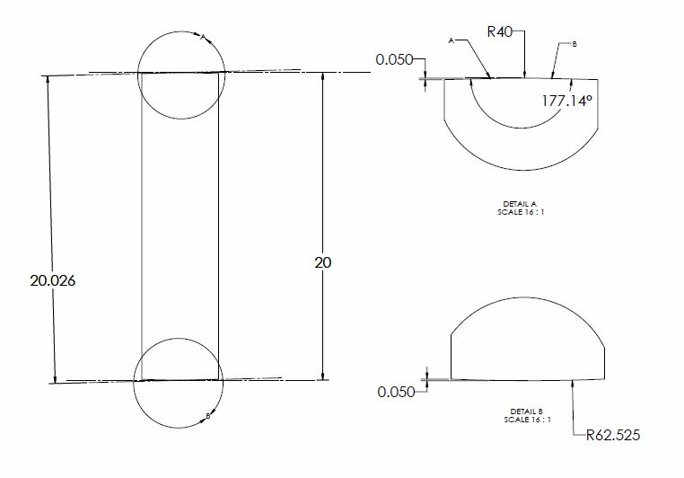
Is something like the below what you had in mind? The bottom surface has constant curvature while the top surface is curved in the middle between points A and B, and has two inclined planar surfaces on either side of A and B. 2 points of contact is achieved at the minimum separation where with 3 points of contact you no longer have a minimum and the UAME is at a perhaps less than optimal or expected orientation.

FOS3_luwati.jpg


Edit: realized I referenced the wrong letters for the points
 
I may be missing something but I can only imagine that a stable minimum envelope for a width feature will always consist of a tangent plane contacting at least 3 high points and a plane parallel to the tangent plane contacting at least one high point.

I am going to ignore the word "tangent" for a moment and concentrate on the "stable minimum envelope" and contact point subject.

For the 2-dimensional case, I will define the following:

Condition 1: One surface contacts the envelope at two points (call these a1 and a2) and the other surface contacts the envelope at one point (call this b1).

Points a1p, a2p, and b1p are the orthogonal projections of points a1, a2, and b1 onto the envelope midline.

Condition 2: Point b1p is between points a1p and a2p.

For the 3-dimensional case, I will define the following:

Condition 1 (option A): One surface contacts the envelope at three points (call these a1, a2, and a3) and the other surface contacts the envelope at one point (call this b1).

Condition 1 (option B): One surface contacts the envelope at two points (call these c1 and c2) and the other surface also contacts the envelope at two points (call these d1 and d2).

Points a1p, a2p, a3p, and b1p (option A) or c1p, c2p, d1p, and d2p (option B) are the orthogonal projections of points a1, a2, a3, and b1 (option A) or c1, c2, d1, and d2 (option B) onto the envelope midline

Condition 2 (option A): Point b1p is within the triangle having points a1p, a2p, and a3p as vertices.

Condition 2 (option B): The line segment connecting points c1 and c2 crosses the line segment connecting points d1 and d2.

I'd say a stable minimum envelope is one that corresponds to a local minimum on the width vs. angle plots I've been posting. Such an envelope will always satisfy conditions 1 and 2. I think it's more useful to look at these conditions as consequences instead of requirements though.


Is something like the below what you had in mind?

In you example, both boundaries of the minimum-width envelope are valid tangent lines. See ASME Y14.5.1M-1994 para. 4.3.2 regarding candidate datum sets for nominally flat datum features, although that definition must be converted to 2D for the examples we're looking at here.

I had in mind a feature such as the following:

[pre]
surface 1:
point 1: (0.00, 0.40)
point 2: (1.00, 0.40)
point 3: (2.00, 0.37)
point 4: (3.00, 0.35)
point 5: (4.00, 0.34)

surface 2:
point 6: (0.00, -0.40)
point 7: (1.00, -0.40)
point 8: (2.00, -0.37)
point 9: (3.00, -0.35)
point 10: (4.00, -0.34)[/pre]

The minimum envelope width is 0.80, obtained with contact at points 1, 2, 6, and 7. For each surface, all contact points are within (1/3)*(4.00-0.00) of one end. This means that neither boundary is a valid tangent plane per the ASME Y14.5.1M-1994 definition.

An envelope width of 0.819836 can be obtained with contact at points 2, 5, and 6 (or 1, 7, and 10), and the boundary that contacts two points is a valid tangent plane. This is the smallest envelope that meets the additional requirement, but it not stable in the sense described above.


pylfrm
 
chez311,
In your latest sketch, boundary 20 would not be stable. It would rock around R40 and R62.535 similarly to the "pure" convex feature scenario we were discussing. Boundary 20.026 would have more points of contact with the faces and therefore more stable, and per my interpretation more in line with the specification "so that it coincides with the surface(s) at the highest points."

pylfrm, thank you for the detailed example.
pylfrm said:
The minimum envelope width is 0.80, obtained with contact at points 1, 2, 6, and 7. For each surface, all contact points are within (1/3)*(4.00-0.00) of one end. This means that neither boundary is a valid tangent plane per the ASME Y14.5.1M-1994 definition.

Would you say that validation according to the candidate datum set method is required for every single case where a tangent plane determination is required? If so, why?
 
I should clarify that the statements about contact points in my previous post are only intended to be valid when the actual part surfaces are seen as finite collections of points, not continuous smooth curves or surfaces.

Also, "onto the envelope midline" should actually be "onto the envelope midplane" for the 3-dimensional case.


Sem_D220 28 Mar 19 08:24 said:
chez311,
In your latest sketch, boundary 20 would not be stable. It would rock around R40 and R62.535 similarly to the "pure" convex feature scenario we were discussing.

I disagree. That is the unique envelope of minimum width, so rocking would not be possible without an expansion of the envelope. Earlier examples behaved differently due to greater curvature of the surfaces. This was illustrated and discussed in the 18 Mar 19 16:54 post by chez311.


Sem_D220 28 Mar 19 08:24 said:
Boundary 20.026 would have more points of contact with the faces and therefore more stable, and per my interpretation more in line with the specification "so that it coincides with the surface(s) at the highest points."

Contact points between actual surfaces in the real world cannot be counted. Contact points between an actual surface and a theoretical envelope can perhaps be imagined, but I don't see how a definition that involves counting them would be useful.


Sem_D220 28 Mar 19 08:24 said:
Would you say that validation according to the candidate datum set method is required for every single case where a tangent plane determination is required? If so, why?

Methods are not within the scope of these standards. Validate the tangent plane with whatever method is appropriate for the task at hand. That doesn't change the definition though.

There's a significant difference between identifying one valid tangent plane and identifying all valid tangent planes. The former is often much easier, but it's not sufficient for determination of the UAME with your proposed interpretation.


pylfrm
 
pylfrm said:
Contact points between actual surfaces in the real world cannot be counted. Contact points between an actual surface and a theoretical envelope can perhaps be imagined, but I don't see how a definition that involves counting them would be useful.

Paragraph 4.10.1 "Development of a Datum Reference Frame for Parts With Planar Surface Datum Features" defines the minimum number of contact points required between each planar datum feature and its datum feature simulator according to the datum precedence order. If the gauging is done physically, I agree that counting the points of contact is not practical and not needed. It is assumed that the defined minimum number of contact points will be achieved mechanically by stabilizing the part on the datum feature simulator surfaces according to the sequence prescribed by the datum precedence order. If the simulation is done with CMM I assume that the number of contact points between a simulated plane and the scanned surface extremities is a parameter in the simulation process, and that is when a definition that mentions the required number becomes useful.

pylfrm said:
Methods are not within the scope of these standards. Validate the tangent plane with whatever method is appropriate for the task at hand. That doesn't change the definition though.

There's a significant difference between identifying one valid tangent plane and identifying all valid tangent planes. The former is often much easier, but it's not sufficient for determination of the UAME with your proposed interpretation.

Perhaps I should have asked my question more directly: For your example of the feature with the specified coordinates, you said that the 0.8 envelope consists of planes which are not valid tangent planes according to the ASME Y14.5.1M-1994 definition because all contact points at each side lie within 1/3 of the surface from the end. I am barely familiar with ASME Y14.5.1M, but recognize the requirement from the projections of all contact points on a line along the simulated plane not to be within 1/3 of the length from the end of that line, as part of the candidate datum set concept. If it is what you meant, why do you apply the candidate datum set requirement on a tangent plane where this tangent plane is not intended to be used as a datum? Would also you require validation of the simulated tangent plane according to candidate datum set for the example shown in fig. 6-18? In the context of UAME simulation for a width feature, considering my interpretation that one of the simulated planes should be a tangent plane, I don't see a reason to treat it similarly to a datum plane.
 
Sem D220 29 Mar 19 12:13 said:
Paragraph 4.10.1 "Development of a Datum Reference Frame for Parts With Planar Surface Datum Features" defines the minimum number of contact points required between each planar datum feature and its datum feature simulator according to the datum precedence order.

Sem D220 29 Mar 19 12:13 said:
why do you apply the candidate datum set requirement on a tangent plane where this tangent plane is not intended to be used as a datum? Would also you require validation of the simulated tangent plane according to candidate datum set for the example shown in fig. 6-18? In the context of UAME simulation for a width feature, considering my interpretation that one of the simulated planes should be a tangent plane, I don't see a reason to treat it similarly to a datum plane.

While it refers to a minimum number of points - the above referenced para 4.10.1 as well as the section about tangent planes (para 6.5) which you referred to in your definition of contact with the high points both refer back to Y14.5.1 for rocking/convex surfaces. The minimum 3 points of contact is the ideal case, but as pylfrm pointed out about my example a convex feature (designed to be flat) can have less than those 3 points of contact and still derive a (or set of) canditate datum plane(s) as well as tangent plane(s). To deal with rocking/convex surfaces in Y14.5.1 there are the sections 4.3.2 (planar) that pylfrm noted, 4.3.3, 4.3.4, 4.3.5 (FOS - RFS/MMC/LMC respectively) - these all deal with datum features and there is no other section as far as I can tell which deals with rocking/convex surfaces. Pylfrm can correct me if I'm wrong, but I think this is why the candidate datum concept is being applied here. It makes sense that this would apply to features which are not datum features as well - if a primary FOS datum is referenced the UAME is the envelope of interest - this should be the same UAME (or set of valid envelopes) if the feature was not referenced as a datum. Note that in several of your responses going as far back as your post on 14 Mar 19 03:46 it seems you have utilized similar logic in relating definition of the UAME to definition of a primary RFS datum - clearly the connection is not lost on you either.

Additionally I don't see anything in this definition of candidate datums about number of points of contact defining a more or less valid candidate datum.
 
pylfrm 28 Mar 19 01:57 said:
In you example, both boundaries of the minimum-width envelope are valid tangent lines. See ASME Y14.5.1M-1994 para. 4.3.2 regarding candidate datum sets for nominally flat datum features,
Thank you pylfrm for pointing this out - I did not make the connection between tangent planes and candidate datum sets until I read this. I was initially responding to Sem's assertion about the number of points of contact, but since your post I'm even less convinced of the need as you pointed out to "count" the number of points of contact.
 
If the simulation is done with CMM I assume that the number of contact points between a simulated plane and the scanned surface extremities is a parameter in the simulation process, and that is when a definition that mentions the required number becomes useful.

Consider a different case: determination of the maximum inscribed sphere for a set of points. There will always be four contact points, but that's just a consequence of the geometry. It would not make sense for the definition of the UAME of an internal spherical surface to explicitly require four contact points.

I'd apply the same argument to external width features. A definition based on minimization of envelope width seems much more meaningful than one based on counting contact points.


If it is what you meant, why do you apply the candidate datum set requirement on a tangent plane where this tangent plane is not intended to be used as a datum? Would also you require validation of the simulated tangent plane according to candidate datum set for the example shown in fig. 6-18?

I think the candidate datum set definition would apply in all cases where a tangent plane is required (including Fig. 6-18) because para. 2.16 (tangent planes) refers to para. 4.11.2 (datum features) which refers to the Y14.5.1M definition.


What do you think the UAME should be for the feature with coordinates posted 28 Mar 19 01:57?


pylfrm
 
Status
Not open for further replies.

Part and Inventory Search

Sponsor