Continue to Site

Eng-Tips is the largest engineering community on the Internet

Intelligent Work Forums for Engineering Professionals

  • Congratulations IDS on being selected by the Eng-Tips community for having the most helpful posts in the forums last week. Way to Go!

Feature Of Size definition

Status
Not open for further replies.

Sem_D220

Mechanical
Jul 9, 2018
290
My first question is - according to ASME Y14.5 2009, how would you classify the cylindrical interrupted surface of diameter 55 and the width 52 in the following sketch?
Are they:
- Regular features of size (with interruptions)?
- Irregular features of size type A? (Or maybe even B?)
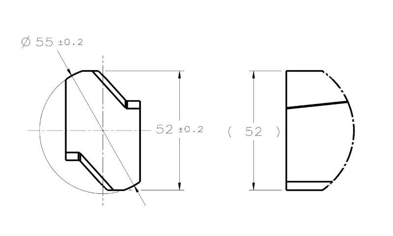
FOS_QUESTION_aejzhn.jpg


My second question is for those who have access to the 2018 standard:
What is the change that was introduced to the concept of feature of size?
I read that there was a change in the concept in the announcement at the ASME website which pmarc linked to in the thread about the new standard.
 
Replies continue below

Recommended for you

Got it pylfrm. I haven't followed this thread carefully, and I just read things quickly.
 
chez311 said:
Even if the part can be fully constrained this would only aid in the determination of the RAME, but would not prevent or limit the pitching/rotating of the UAME as it contracts around the feature.

If the part is fully constrained, I hope we agree that the feature itself would not be able to pitch/rotate during simulation of the UAME (this is what I initially thought you were referring to).
The UAME would be able to rotate and translate (edit: and obviously contract) during the simulation until it becomes "a similar perfect feature(s) counterpart" which I interpret as 2 parallel planes making maximum possible contact with the high points of the feature, i.e. with both planar surfaces nominally 52mm apart. Once it complies to this definition/requirement, I think it is fully defined and determinable. What are your objections to that?
 
Belanger, I think you actually understood my point pretty well originally, as I was talking in the context of UAME simulation during Position/Orientation controls - including the statement pylfrm quoted.
 
Sem D220 13 Mar 19 07:52 said:
I was talking in the context of UAME simulation during Position/Orientation controls
As far as I am aware of, there is only one definition of UAME which is wholly independent of what control is utilized, material condition/boundary modifiers, what the DRF looks like or if there is 0, 1, 2, 3, etc.. datum(s) called out - it does not matter, none of these things affect the resulting UAME.

Sem D220 13 Mar 19 06:45 said:
If the part is fully constrained, I hope we agree that the feature itself would not be able to pitch/rotate during simulation of the UAME
This is where we differ. It wouldn't be the feature/part itself which pitches/rotates/translates during simulation but the UAME boundary. The specified DRF has no impact on this regardless of whether the part is unconstrained or fully constrained.

Sem D220 13 Mar 19 06:45 said:
The UAME would be able to rotate and translate (edit: and obviously contract) during the simulation until it becomes "a similar perfect feature(s) counterpart" which I interpret as 2 parallel planes making maximum possible contact with the high points of the feature, i.e. with both planar surfaces nominally 52mm apart
The definition of the UAME has no requirement that there be maximum possible contact, or specify any importance of a nominal dimension. I think the driving part of the definition is that it is the boundary (similar perfect feature(s) counterpart) of "smallest size that can be contracted about an external feature(s) or largest size that can be expanded within an internal feature(s)" - ie: the UAME continues to contract/expand until its reached its smallest (minimum) or largest (maximum) size respectively. Perhaps someone else can support/refute this but I believe the reference to the fact that it "coincides with the surface(s) at the highest points" is not a requirement for maximum contact of any sort but instead a clarification/refinement to the requirement that the boundary exist wholly outside the material.

ASME Y14.5-2009 said:
1.3.25 Envelope, Actual Mating
envelope, actual mating: this envelope is outside the
material. A similar perfect feature(s) counterpart of
smallest size that can be contracted about an external
feature(s) or largest size that can be expanded within an
internal feature(s) so that it coincides with the surface(s)
at the highest points. Two types of actual mating envelopes
— unrelated and related — are described in paras.
1.3.25.1 and 1.3.25.2.

1.3.25.1 Unrelated Actual Mating Envelope.
unrelated actual mating envelope: a similar perfect feature(s)
counterpart expanded within an internal feature(s) or
contracted about an external feature(s), and not constrained
to any datum(s).
 
chez311 said:
the UAME continues to contract/expand until it reached its smallest (minimum) or largest (maximum) size respectively.

The moment when it reaches it's smallest/largest size is the exact time when it contacts the surfaces at the highest points - there can be no other situation physically unless we constrain the UAME directly to some external reference, and we agree that we don't. And - in the same moment mentioned above, the UAME is constrained by the feature itself (which in turn is constrained by the DRF and is unable to rotate). Once again: the actual feature is constrained in movement by the DRF. The UAME is constrained by the feature when it reaches its' smallest size (for external feature) AND touches the feature on the highest points.
 
Sem D220 13 Mar 19 10:07 said:
the actual feature is constrained in movement by the DRF

Sem D220 13 Mar 19 10:07 said:
The UAME is constrained by the feature when it reaches its' smallest size (for external feature)

These two things are mutually exclusive. The DRF and accompanying constraint of the feature has no impact, directly or indirectly, on the definition/derivation of the UAME - the UAME remains the same if 0 DOF or 6 DOF are constrained. The way I read it, your statement suggests some indirect impact/constraint of the UAME resulting from the specified DRF, which is not the case.
 
I was merely describing the physical conditions that are present during the UAME simulation. The bottom line and the message I wanted to convey is that there shouldn't be any rotation or pitching during the UAME simulation of the considered feature. The UAME can't rotate with the feature because the feature is constrained, and it can't rotate relative to the feature because there is only one way it can reach minimum parallel planes separation while contacting the surfaces of the feature.

Let me ask you this - let's call the two plane surfaces nominally 52mm apart "indirectly opposed" as you suggested. What advantage does a "directly opposed" width feature have over this feature? Why the UAME for a "directly opposed" feature can't rotate/pitch, whereas this one can't can?
 
The UAME can't rotate with the feature because the feature is constrained, and it can't rotate relative to the feature because there is only one way it can reach minimum parallel planes separation while contacting the surfaces of the feature.

What are you suggesting defines a minimum separation? If your answer is still "maximum possible contact", please provide a definition for that term. Also, please explain the connection between what you suggest and the text of the standard.


pylfrm
 
"Minimum separation" means the minimum achievable distance between parallel planes as they contact the surfaces of the feature. This condition is achieved when the maximum contact exists between the UAME simulator and the feature, although the definition of the term Actual Mating Envelope (Y14.5 2009 para. 1.3.25) in the standard only mentions contact on the highest points without explicitly requiring "maximum" contact. "Maximum contact" is mentioned in a paragraph that describes a closely related concept - simulating a datum center plane of a feature of size referenced RMB:

ASME Y14.5 para. 4.11.4 said:
(b) Primary Datum Feature: Width RMB. The datum is the center plane of the datum feature simulator of the datum feature. The datum feature simulator (or unrelated actual mating envelope) is two parallel planes at minimum separation (for an external feature) or maximum separation (for an internal feature) that makes maximum possible contact with the corresponding surfaces of the datum feature. See Figs. 4-3, illustration (b)

As you can see, the definition itself includes a clarification in parenthesis that the simulation of a datum center plane is essentially establishment of an unrelated actual mating envelope and both "minimum separation" and "maximum possible contact" are mentioned in the same sentence. Analogical descriptions appear for cylindrical and spherical datum features in the same paragraph.
 
Sem D220,

I can see what you're getting at, with the idea of defining the UAME in terms of maximum contact between the feature and a perfect-form counterpart. I agree that this would be a better way to define the UAME. The current definition was based on simple well-behaved features of size like fully opposed cylinders and widths. For these features, it happens that the size of the envelope is maximized (or minimized) when maximum contact is achieved. So it worked well enough to define the UAME in terms of the size of the simulator (or the separation of the planes in the case of the width feature). When we start looking at less ideal features like the unopposed planar surfaces or unopposed partial cylinders, maximizing (or minimizing) the size of the simulator doesn't work - because the important thing is the maximum contact.

Y14.5 has introduced the idea of maximum contact as you have pointed out, but there is still a ways to go. First, the term "maximum contact" is used in certain definitions (see Fig. 4-31 (a) in Y14.5-2009) but the meaning of the term is not defined.

I would say that Y14.5.1 will lead the way with improvements to the definition of maximum contact.

Evan Janeshewski

Axymetrix Quality Engineering Inc.
 
Thank you for the input axym.
You said:

"When we start looking at less ideal features like the unopposed planar surfaces or unopposed partial cylinders, maximizing (or minimizing) the size of the simulator doesn't work - because the important thing is the maximum contact."

If we deal with the case of the 52mm unopposed width from the sketch I posted, ignoring the addition of "maximum contact" condition at simulation and only base the verification process on the pure definitions of AME and UAME specifically in paragraphs 1.3.25 and 1.3.25.1, do you think that there might be a case where bringing the simulator planes to minimum separation about the feature will not result in repetitive and determinable result? If yes, is it any different with simple opposed width features? The reason I'm asking is that after examining it more closely, I no longer stand by my previous statement that there can only be one way to bring the simulator to a minimum separation about the feature. For example, where both surfaces of the feature are produced slightly convex, there could theoretically be 2 different orientations at which the UAME simulator can contract to the same size of minimum separation (maximum separation for this case would be when the simulator contacts the peaks at the central areas of the slightly convex surfaces). But - and this is the important point - the same issue can easily occur for regular opposed width features of size. So, I have yet to be convinced that the unopposed geometry can be the cause for unstable UAME simulation and consequently disqualify this type of features from being considered features of size.

The only essential difference I see between this type of features and regular features of size is the lack of an "Actual Local Size" per para. 1.3.54 at Y14.5-2009. But, the existence of actual local sizes is not a requirement that a feature must conform to in order to be considered a feature of size per the definitions in the subparagraphs of 1.3.32. If the UAME is determinable, and I am yet to be convinced that it's not, why feature-of-size related applications such as Position control can't be utilized for such features?
 
Sem_D220,

Maybe this will help:

Shortly speaking, because the lower feature doesn't have opposed points, a gage simulating actual mating envelope of that feature is able to contract to the much smaller size than the shortest distance between two perfectly flat (not even slightly convex) faces constituting the considered feature. As chez311 mentioned in one of his previous replies, if instead of 2 there were 3 offset (at distance 52) planar features lacking opposed points (like for example datum feature A in fig. 4-33 in Y14.5-2009), the contraction would have to stop at 52, similar to the case of regular FOS shown in the upper portion of the attached graphic.
 
Sem,

My apologies. I was running out of ways to describe what I meant purely with words and did not have time yesterday to come up with a few cases and put them into figures. Hopefully the ones I have now made will communicate what I am trying to say and not confuse the issue further.

First off I want to reiterate/address something which I think is important and sort of preclude any discussion of maximum contact/UAME definition.

Your main premise starting with your post on (9 Mar 19 07:36) was that since the part could be fully constrained to a DRF during simulation, a UAME could be defined. I apologize for beating a dead horse but I think it bears repeating - it does not matter if the part is constrained, partially constrained, or unconstrained - the UAME definition will not change. If it did, it would violate the definition of UAME which does not involve datum references. If you want to attack it from a different angle by attempting to define maximum contact instead then I that is a different matter - I believe I still disagree, but at least I can see the merits of the argument.

See my attached figure for three cases.
Case #1 - offset faces are flat and parallel
Case #2 - offset faces are flat and non-parallel
Case #3 - offset faces are convex

In case #1, my assertion that the UAME boundary can progress without limit (1B*) so there is no "minimum size" and is therefore indeterminate. I understand your point about maximum contact but it is not in the definition of UAME and regardless is not well defined (if at all).

My case #2 further highlights this point. Where is maximum contact in your opinion? Is it 2B* or 2C*? Each has the same amount of contact, however 2C has a smaller envelope. As with case #1 there is no limit to the progression (and no minimum size limit to the UAME) so I say the UAME is still indeterminate.

For my case #3 I assert still that there is no limit to progression, now with no definable "maximum contact" as the UAME progresses the amount of contact never changes.

Sem D220 14 Mar 19 17:46 said:
For example, where both surfaces of the feature are produced slightly convex, there could theoretically be 2 different orientations at which the UAME simulator can contract to the same size of minimum separation (maximum separation for this case would be when the simulator contacts the peaks at the central areas of the slightly convex surfaces)
This would be my case #3. I believe there is no limit to progression and not 2 different orientations as you suggest.

Sem D220 14 Mar 19 17:46 said:
But - and this is the important point - the same issue can easily occur for regular opposed width features of size.
**

I'm actually not convinced this is the case. I had the same thought however after doing some quick modelling/sketching in CAD I explored some options such as a barrel-shaped convex feature with opposed points and there was always a single defined minimum separation of the UAME. If you can develop a figure which shows otherwise could you share it?

*Edit: a few incorrect references to my own figures

**Edit2: deleted some repeated portions of a quote
 
 https://files.engineering.com/getfile.aspx?folder=757fbd93-4ccb-497c-91c2-b6402f3798f9&file=nonFOS_-_examples.PDF
I saw a few replies as I was in the process of putting together this post. I also made a few edits - I hastily hit submit.

Sem - I apologize if you have shifted your thinking or changed your position in regards to the points I address. If so please kindly correct me where I may have missed the mark.

pmarc - I hope my figure is not too redundant, I read your post and I thought it was still worth sharing. You illustrate the point I was trying to make yesterday but did not have the time to put together figures to communicate clearly. Thank you.
 
Thank you pmarc and chez311 for the clear figures.
I understand the points you convey, but I still suspect that similar issues (of unrestricted contraction) may occur with regular opposed features of size, given that we take "maximum contact" out of the equation. In 2 or 3 days from now when I have access to CAD again I will check this and update, and if what I imagine is correct, I will post the relevant figures.

chez311 said:
Your main premise starting with your post on (9 Mar 19 07:36) was that since the part could be fully constrained to a DRF during simulation, a UAME could be defined. I apologize for beating a dead horse but I think it bears repeating - it does not matter if the part is constrained, partially constrained, or unconstrained - the UAME definition will not change. If it did, it would violate the definition of UAME which does not involve datum references

chez311, I feel it's time this misunderstanding gets clarified. You are not beating a dead horse, you are preaching to the choir :)
In the post you refer to from 9 Mar 19 07:36 I clearly said:

"The thing to realize is that the part is constrained, but the simulated UAME is not constrained to the DRF, it merely follows the as-produced feature"

On 13 Mar I repeated:

"Again, the UAME is never constrained to any datums, but the part during UAME simulation is (in this case)."

I believe I said similar things in a few more occasions in this thread later. The reason I brought up the part being constrained by the DRF in this discussion is that it seemed to me that the main support for the claim about unstable UAME simulation was originally the possible movement of the part/feature during contraction of the UAME simulator. This idea was clearly described in the quote supplied by Kedu from the LinkedIn discussion:

"E and F are not irregular features of size either. For these two be irregular features of size the mating envelope - two parallel planes - would need to able to close down on these faces. With these geometry closings parallel planes about the part surfaces would pitch ( or rotate) the part and would not actually close down on these faces.”

In response to this quote you said:

This is what I meant by "I don't think it will be able to properly constrain a mating envelope" since as the boundary closes down the feature will rotate as that boundary closes in, as it is not stable, having no opposed elements.

It appears that later, you changed your perspective and approached the UAME instability issue differently:

This is where we differ It wouldn't be the feature/part itself which pitches/rotates/translates during simulation but the UAME boundary.

Prior to that restatement, I was already commenting on the original claim and my point was, that if the part/feature is constrained per the DRF during the inspection which involves simulating a UAME, the issue described (movement of the part) is irrelevant. To add to that I'd like to say now that as much as the UAME simulation should be independent of the referenced datums by definition, it should also be independent of phenomena such as uncontrolled rocking/wobbling/pitching/rotation of the part as the result of the forces acting on it during the inspection.

Edit: added some paragraph spacings for easier reading.
 
Hi All,

pmarc's figures illustrate exactly what I was thinking. The upper example with the I-beam shape is the type of well behaved geometry that Y14.5's minimum-separation definition works well on. The unopposed geometry in the lower example makes the definition fail. The B figure represents what I was thinking with the maximum contact.

Evan Janeshewski

Axymetrix Quality Engineering Inc.
 
pmarc, axym,

Illustration C for the unopposed geometry in pmarc's feature figure shows the part tilted relative to its' previous condition at illustration A and B. To me this suggests that the failure in UAME simulation happens because of a degree of freedom that the part has. As I mentioned I do realize that no datum constraints should affect the UAME simulation result, but the simulation should neither be affected by any degrees of freedom that the part has and the forces applied to it during an inspection. Am I wrong?

I'm aware that essentially it doesn't matter if the part is rotated relative to the simulator or the simulator is rotated relative to the part. I could tilt my head to the side when looking at illustration C and view it as if the simulator was rotated relative to the part and not the other way around. Nevertheless, (edit: no matter what rotates and what stays at constant orientation in the part - simulator interaction), I do think it is a point worth looking into because there are procedures that are intended to prevent the effect of forces in inspection and perhaps the problem can potentially be avoided altogether. I believe there is a paragraph in ASME Y14.43 dealing with the issue.

As promised I will try to make figures of my own in the next few days if my suspicion that similar issues may occur with regular opposed features will turn out justified.

 
Sem,

I caught your comments about the UAME not being constrained to any DRF, which made your assertions that inclusion of a DRF and constraint of the part would enable the derivation of a mating envelope all the more confusing. I did not catch my own change in wording - for me the frame of reference was inconsequential as long as I kept in mind that inclusion or removal of datum references would have no effect on establishment of the UAME. Your statement that "essentially it doesn't matter if the part is rotated relative to the simulator or the simulator is rotated relative to the part" is what my thought process was the whole time. I should have been more consistent in my wording and/or caught that and clarified myself.

Sem D220 15 Mar 19 09:00 said:
As I mentioned I do realize that no datum constraints should affect the UAME simulation result, but the simulation should neither be affected by any degrees of freedom that the part has and the forces applied to it during an inspection. Am I wrong?
I think I agree with you here. This would be the physical reality of the theoretical specification that datum references are not involved in establishment of the UAME. That is as long as you mean forces/constraints as it applies to any datum features on the part.

In regards to maximum contact, I have always had a problem with the fact that this term was continually utilized in the standard yet never defined. Without this we are continually left to wrestle with what it means in different circumstances - in lieu of this definition I have typically taken it to mean that it progresses until it cannot progress any further. Any other definition creates constraints which may stop progression before that point, this could be acceptable if it is clearly specified somehow, but not in my mind going solely by the content in the 2009 standard. By a brief skim of the 2018 standard it does not look like much clarity is provided - though I will have to take Evan's comment into account and do a more thorough read through of the Y14.5.1 draft and see what clarity may have been imparted.

I am interested to see what you come up with for a purportedly more "well behaved" FOS (as Evan called it) having opposed points. I can perhaps see situations where there might be multiple solutions (probably 2, maybe more) but none analogous to the one in your initial post which I believe has no solution.
 
chez311 said:
I caught your comments about the UAME not being constrained to any DRF, which made your assertions that inclusion of a DRF and constraint of the part would enable the derivation of a mating envelope all the more confusing.

chez311,
I'm sorry if I put my ideas into words in a confusing way. But the message I try to express about the effect of DRF is consistent throughout. The DRF is not part of the UAME definition. But, where it participates in the inspection process, it may prevent the phenomenon that was argued (not by me) to be the cause of infeasible UAME simulation. This phenomenon is the uncontrolled movement of the part as a result of forces that the simulator exerts on the part. If we accept that this is a legitimate argument, then the DRF being part of the picture during UAME simulation can be brought up as a counterexample. In that specific context, the fact that it is the part/feature which was pointed to as the unstable (rotating/pitching) element in the process matters - obviously because the DRF affects the part, but never the UAME . Again, all of the above is relevant only if we look at the "rotating part" issue as a legitimate reason to dismiss unopposed features as non-features-of-size.

The additional point I was suggesting to examine in my recent posts, is that the relative movement between the part and the simulator is irrelevant altogether to the whole concept of the definition of the feature of size. That is because the presence of degrees of freedom and the ability of forces during inspection to cause movement should not affect the UAME, as all these are not part of the UAME definition, just as datums are not. In this specific context, it doesn't matter if the part is rotated relative to the UAME or the UAME is rotated relative to the part. I suggest questioning the relevance of relative movement generally to the subject.

Hope this clears up some of he confusion that was apparently caused by my previous posts. And I apologize for causing that confusion.
 
Sem D220 15 Mar 19 15:43 said:
The DRF is not part of the UAME definition. But, where it participates in the inspection process, it may prevent the phenomenon that was argued (not by me) to be the cause of infeasible UAME simulation. This phenomenon is the uncontrolled movement of the part as a result of forces that the simulator exerts on the part. If we accept that this is a legitimate argument, then the DRF being part of the picture during UAME simulation can be brought up as a counterexample.
I do not agree with this. I accept that there are realities in the physical world with inspection that make holding precisely to the theoretical concepts outlined in this (and other) standards difficult - however the setup must account for that as much for that as possible. If the UAME must be simulated (which it does not always - say for most MMC/MMB situations) then it might require an additional setup/gauge/fixture - the datum features should not be allowed to limit any DOF in this instance, within reason of course I accept there could be limitations to what is possible.

Sem D220 15 Mar 19 15:43 said:
The additional point I was suggesting to examine in my recent posts, is that the relative movement between the part and the simulator is irrelevant altogether to the whole concept of the definition of the feature of size. That is because the presence of degrees of freedom and the ability of forces during inspection to cause movement should not affect the UAME, as all these are not part of the UAME definition, just as datums are not.
I'm not really sure how to address this, or what this adds to the discussion about establishing a UAME for features of this type. I'm going to try my best to answer it but I'm not sure I'm going to succeed. Perhaps someone else can pick up the slack where I may be lacking. Here goes:

Relative movement of the simulator and feature and the forces exerted as a result (though hopefully very small in order to minimize deflection) is just a result of the physical realities of simulating a theoretical boundary (UAME) with a physical part (simulator/gauge), pursuant to the limitations I noted above. I guess in theory this boundary would be coincident with the surface and is inseparable - ie: does not have to be brought into contact and instead coexists with the surface of the feature, that is if it even exists (as in the case where there is no solution). Relative movement is also an easier way for us as humans to visualize some of these situations (I know it is for me). I think I understand what you are saying, essentially if there is a solution which achieves "maximum possible contact" with a feature then this could define a boundary even if an imbalance of forces would exist with a physical gauge/simulator (ie: is not a stable equilibrium) - however "maximum possible contact" is not defined in the standard so I'm not sure where you would go with that. You could come up with your own specification for this if desired or call out a particular fitting routine.
 
Status
Not open for further replies.

Part and Inventory Search

Sponsor