Continue to Site

Eng-Tips is the largest engineering community on the Internet

Intelligent Work Forums for Engineering Professionals

  • Congratulations IDS on being selected by the Eng-Tips community for having the most helpful posts in the forums last week. Way to Go!

Feature Of Size definition

Status
Not open for further replies.

Sem_D220

Mechanical
Jul 9, 2018
290
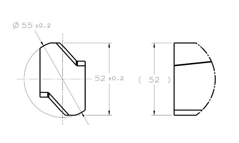
My first question is - according to ASME Y14.5 2009, how would you classify the cylindrical interrupted surface of diameter 55 and the width 52 in the following sketch?
Are they:
- Regular features of size (with interruptions)?
- Irregular features of size type A? (Or maybe even B?)

FOS_QUESTION_aejzhn.jpg


My second question is for those who have access to the 2018 standard:
What is the change that was introduced to the concept of feature of size?
I read that there was a change in the concept in the announcement at the ASME website which pmarc linked to in the thread about the new standard.
 
Replies continue below

Recommended for you

chez311 said:
If the UAME must be simulated (which it does not always - say for most MMC/MMB situations) then it might require an additional setup/gauge/fixture - the datum features should not be allowed to limit any DOF in this instance

What do you suggest to do for simulation of a UAME of an inspected feature as part of position RFS or center plane/axis orientation RFS control? Without establishing the DRF the tolerance zone is undefined. How do you suggest to verify those tolerances without limiting the degrees of freedom of the part? Maybe I misunderstood your statement, if so please clarify.

Regarding the second point - perhaps there is another way to apply an unambiguous UAME solution, without demanding "maximum contact" which is apparently not well defined and not part of the definition. Also considering that we insist on not simulating a controlled feature's UAME the same way we derive datums from datum features of size (para. 4.11.4 which requires maximum possible contact). The other way I'm suggesting is looking at the term "a similar perfect feature(s) counterpart" which is part of the definition and appears at para. 1.3.26. How should the term "similar perfect feature counterpart" interpreted and can it imply a definitive single solution? Looking for more details I found out that Alex Krulikowski defines it as a "boundary that is the perfect inverse of the feature" (Fundamentals of Geometric Dimensioning and Tolerancing). In the same source, he also writes that an actual mating envelope is "a similar perfect feature counterpart that would surround the high points of a feature of size". From this and from the definition in the standard I get the impression that contraction to the minimum size about an external feature or expansion to the maximum size within an internal feature is not the only, and perhaps not even the main role of the UAME. More specifically, there is a limit until which the UAME simulator of any feature can contract/expand without becoming noncompliant to the specification of being a similar perfect feature counterpart - which actually means staying as adjacent as possible ("perfect inverse") to the feature.

If my personal opinion matters, I still say that the most rational way to approach this is to simply follow paragraph 4.11.4 for every case where a UAME should be simulated. I may not have a solid argument here to back it up, but my logic tells me that there is no reason to treat the derivation of an axis or a center plane of a feature that should be controlled for location or orientation differently than the derivation of a datum axis or center plane. I'd like quote part of this paragraph once again:

"(b) Primary Datum Feature: Width RMB. The datum is the center plane of the datum feature simulator of the datum feature. The datum feature simulator (or unrelated actual mating envelope) is two parallel planes at minimum separation (for an external feature) or maximum separation (for an internal feature) that makes maximum possible contact with the corresponding surfaces of the datum feature. See Figs. 4-3, illustration (b);
4-13; and 4-14."
 
This is just my opinion, but this thread is a great example of why the standard should show (for example in an appendix) some examples of features that are not regular and irregular features of size. I realize it is impossible to show all cases one can ever imagine, but showing some of the most common scenarios definitely wouldn't hurt.
 
The image shows 2 cases comparable with Case #2 and Case #3 in the figure by chez311. The same issues that were associated with non-opposed geometry occur for features designed to be "well behaved" opposed feature of size. Left sides shows a feature produced with slightly convex faces, and 2 possible candidate UAMEs at different orientations. This is the "well behaved" equivalent to Case #3. Right side shows a feature with the faces produced slightly non-parallel. This is the "well behaved" equivalent to case #2.

UAME_vckg11.jpg
 
Sem_D220,

If we, for example, take you picture on the right:
1. What makes you think that the 19.49 envelope is really the UAME of the as-produced 20 feature?
2. More important, is further contraction of the 19.42 envelope possible?
 
pmarc,
I never said that 19.49 is the correct size of the UAME.
The following figure should answer your questions:
UASME_ANSWERS_bsftyx.jpg
 
Sem_D220,

1. Ok. I simply wanted to make sure that you did not consider the 19.49 envelope good candidate for UAME.

2. I personally do not think that the '19 or less' envelope is good candidate for UAME too. It is basically because the as-produced 20 feature is not fully constrained/immobilized relative to that envelope. To achieve full immobilization, the envelope would have to contact the feature in at least 3 points in the shown view (2 on one face and 1 on second face). For the proposed as-produced geometry, it is the 19.42 and the 19.49 envelopes that satisfy this condition, but because the 19.42 envelope is smaller of the two, it is the correct UAME of the feature.

This is how I understand maximum possible contact with the corresponding surfaces of a planar (two-parallel-planes) feature of size.
 
pmarc,
Just to clarify in case someone may misunderstand, the number 19 ("or less") was randomly chosen to be shown as an example. If we go purely by the UAME definition as was advocated by numerous responses in this thread then "maximum contact" is not part of the considerations and therefore any value below 19.49 19.42 and above the width of the feature (for example - 5) would be a legitimate candidate too, and could be chosen as an example for the answer on your question: "is further contraction of the 19.42 envelope possible?"

Per my understanding, not even the 3 point contact you described would save the situation, because technically all three points of contact can be located on the edges intersecting the top/bottom faces and the 2 left/right surfaces. For example - 2 points on the edge between top & right and one point on the edge between bottom & left, for the 19 UAME shown. I agree that this kind of contact would not immobilize the feature relative to the envelope, as you say. The same is true for the <52 envelope in illustration C for the unopposed feature which you posted above. Both envelopes are equally appropriate or inappropriate.

For immobilizing the feature, the unrelated actual mating envelope has to do more than just contracting to the smallest size about the external feature until further contraction is impossible. It has to be sufficiently adjacent to the feature as well. Whether the faces the feature consists of are opposed or non-opposed doesn't seem to matter in this context.
 
Sem_D220 said:
Per my understanding, not even the 3 point contact you described would save the situation, because technically all three points of contact can be located on the edges intersecting the top/bottom faces and the 2 left/right surfaces. For example - 2 points on the edge between top & right and one point on the edge between bottom & left, for the 19 UAME shown.

If you read my last reply again, you will notice that I said that at least 3 points of contact would be required in the shown view. What you described, as quoted above, doesn't satisfy this condition.


Sem_D220 said:
The same is true for the <52 envelope in illustration C for the unopposed feature which you posted above. Both envelopes are equally appropriate or inappropriate.

I disagree with that for the reasons I already explained in my previous comments.
 
pmarc, I'm sorry for missing that you said that all 3 points of contact should be in the shown view. I hope you don't mind answering on these 3 questions:

1. We are dealing with a 3-dimensional feature and a 3-dimensional UAME, how do the 3 points of contact in a shown view prevent the same problem (of the UAME and the part not being constrained to each other, and the unrestricted contraction of the UAME simulator) from occurring with rotation around another axis in a way that can be visualized on another drawing projection?

2. How is the "3 points of contact" concept implied by the UAME definition in the standard? The background to this question is that I was told that "maximum possible contact" shouldn't be required during UAME simulation as it isn't part of the definition. And since it isn't required, UAME simulation might fail - but only for unopposed features.

3. Considering that the issue described in the first question can somehow be resolved or there is no issue at all and it is me who fails to see it (quite probable), why can't the same concept be implemented on unopposed features such as in the second row of the illustration you posted above? If this is already covered in your previous posts, I apologize for missing this too.
 
1 and 2. The concept of 3 points of contact in shown view was introduced just to picture that the feature should be immobilized relative to its true UAME. And of course because we are talking 3D, the same logic applies in the side view (I thought this did not have to be explicitly stated). 

The key thing here is that as long as in any of the two views the 3 points of contact are seen as 2 points, there will be an instability of the feature relative to the envelope. In other words, the envelope will not be such that it "coincides with the surface(s) at highest points", as given in the UAME definition.

3. Yes, it has been already covered by me. It is not the concept of 3 points of contact that really matters in case of a feature having non-opposed surfaces. It is the idea that there is no way to fully immobilize the feature relative to the contracting envelope because there is nothing that physically stops the contraction of the envelope.

As pointed out by chez311, physical reality is what should really matter here. This should also drive the classification of a feature as FOS or non-FOS. Definitions in the standard should go hand in hand with the reality, but, as it was already mentioned, they unfortunately do not always work well for cases other than "well behaved" geometries produced as well behaved shapes. 
 
pmarc,
Now that I realize that the 3 points idea is not view dependent, I think this is the definition for "maximum possible contact" that is missing in the standard as was pointed out by axym, chez311 and possibly others. Perhaps such definition is not required and as you pointed out - 3 points of contact is the true meaning of the sentence "coincides with the surface(s) at highest points" and this specification should simply not be neglected. That is because as I've shown in the figure from 17 Mar 19 10:11, if this specification is not followed, even the UAME for a simple feature designed as a "well behaved" geometry, and possibly produced within all tolerances, might not have a solution.

pmarc said:
It is not the concept of 3 points of contact that really matters in case of a feature having non-opposed surfaces. It is the idea that there is no way to fully immobilize the feature relative to the contracting envelope because there is nothing that physically stops the contraction of the envelope.

I'm sorry but I am still not getting it.
I have clearly shown that without the "maximum possible contact" or if you prefer "the 3 points of contact method", the statement "nothing that physically stops the contraction of the envelope" is equally relevant to simple "well behaved" features of size. Why would the 3 points method prevent the failure of UAME size < 19.42 from my figure from 17 Mar 19 10:11, but not the failure of UAME size < 52 from your figure from 14 Mar 19 18:23?

Edit: grammar correction
 
Sem D220 15 Mar 19 22:16 said:
What do you suggest to do for simulation of a UAME of an inspected feature as part of position RFS or center plane/axis orientation RFS control?
As for a physical gauge, I would really defer to someone with more experience in gauging - however I do know that this is one of the main reasons that gauges for RFS position are much more expensive. The first thing that comes to mind though is an expanding pin - this could be utilized to simulate the UAME of an RMB primary datum feature and could touch/constrain other features and DOF as long as it was expanded within the primary datum feature first. Another could be a free floating expanding pin which is inserted and expanded within a hole and does not contact any other features - this could be utilized to find the size of the UAME (or a series of solid plug/pin gauge could be inserted until one is found which just fits - this would provide a similar function). As far as how to utilize this simulated UAME to gauge RFS position I would let someone more experienced than I answer that.

Sem D220 15 Mar 19 22:16 said:
Without establishing the DRF the tolerance zone is undefined. How do you suggest to verify those tolerances without limiting the degrees of freedom of the part?
UAME =/= tolerance zone. The UAME must fall within the established tolerance zone - or in the case of a primary datum feature, it establishes the DRF from which other features are derived.

Sem D220 15 Mar 19 22:16 said:
If my personal opinion matters, I still say that the most rational way to approach this is to simply follow paragraph 4.11.4 for every case where a UAME should be simulated.
I do not see how this helps clarify matters considering the additional term "maximum possible contact" is still not defined within the bounds of the standard. As far as I'm concerned, the 3 points of contact is just a result of maximum expansion/contraction/progression of the boundary to reach its largest (for an internal feature) or smallest (for an external feature) size. Even if 3 points of contact can be established before then (in your example - the 19.49 boundary) it is not the UAME unless it has reached its smallest size (the 19.42 boundary).

In regards to your two features, for the second one I agree with pmarc that the correct UAME is unambiguously 19.42 - your alternative "19 or less" is not valid. If you consider contraction of the boundary as it progresses towards its minimum separation, 19.42 is the only solution - to achieve a smaller boundary (your "19 or less") it is no longer only contracting but also rotating arbitrarily away from the surfaces being simulated.* Conversely this would also happen if you were starting contraction with the part at an excessive angle such that it closed down on the longer 2x faces instead of the shorter 2x faces in question.

In regards to your first figure, I was intrigued as to why I did not see that on my initial, admittedly quick, look at the geometry. It looks like with features of a high length to width ratio as you have shown, with relatively loose tolerances (not unreasonably so - but definitely not very tight) on the size/form an unstable situation could arise. If I have some time I might come up with a formula to show the relationship, but in the meantime the below figure shows that in order to create the situation you showed it requires the center of the arcs which make up the barrel shape to be at some separation from each other, which also requires a relatively small radius on each side resulting in a relatively large size/form deviation. If these arcs are changed so that their centers are coincident then the feature essentially now becomes round and there is no minimum as the separation becomes the diameter and is the same at every point. If these arc centers cross the centerline then there is now a minimum at the apex of each arc and the feature now becomes "well behaved" - as the size/form tolerance gets tighter this would only become more true. I don't know how often one might encounter this as it requires a specific set of conditions, and I do not know exactly how this would be handled in regards to establishing a UAME - however I do not think it is perfectly analogous to your OP example as they are not "unstable" in the same sense - ie: I think you would find that if you contracted a physical boundary about my case #2 below I think you would find it relatively stable, despite having no minimum. The same could not be said for your OP with offset planar features.

Note the difference in the size/form deviation of each feature (.462 / .318 / .310 respectively). As I stated if this is minimized by a tighter tolerance, this instability and lack of defined singular minimum disappears.

unstable_FOS_hdaz8c.jpg


*I know I stated in my reply (15 Mar 19 18:19) that theoretically these boundaries would coexist with the surface and maybe downplayed the physical realities, based on pmarc's replies and thinking about it some more I think I was on the right track initially by focusing on the physical realities of simulation.

**Edit - made the figure more readable, I realize that the dimensions may have been hard to read.
 
chez311, I'm not experienced in gaging either, but I think that the idea of checking position RFS or center plane orientation RFS of a feature of size is simulating the UAME while the part is constrained at the datum features at the fixture, and its' degrees of freedom are constrained as implied by the DRF specified in the drawing. When the UAME is simulated under these conditions, the derived feature axis or center plane (the product of the UAME simulation) is checked for fitting within the tolerance zone, which can only be determined based on the datum feature simulators.

chez311 said:
If you consider contraction of the boundary as it progresses towards its minimum separation, 19.42 is the only solution - to achieve a smaller boundary (your "19 or less") it is no longer only contracting but also rotating arbitrarily away from the surfaces being simulated

How would you comment on the suggestion that the boundary of 39.030 for Case #2 of the unopposed feature from your post at 14 Mar 19 18:46 is also the only solution for that case? 47.444 is not the UAME size as it is possible to contract the envelope further without losing proper contact relationship with the feature. Less than 39.030 - unacceptable rotation and loss of contact occurs just like with the "simple" opposed feature. What is the essential difference?

chez311 said:
I think you would find that if you contracted a physical boundary about my case #2 below I think you would find it relatively stable, despite having no minimum.

I wouldn't call it stable because even though the size of the UAME stays constant the orientation of the UAME (and therefore the orientation of the feature center plane) can differ from one simulation to another. If the purpose is to check if it falls within a tolerance zone or not, there is going to be trouble.
 
Sem D220 18 Mar 19 17:51 said:
but I think that the idea of checking position RFS or center plane orientation RFS of a feature of size is simulating the UAME while the part is constrained at the datum features at the fixture, and its' degrees of freedom are constrained as implied by the DRF specified in the drawing.
This would no longer be the UAME. It would be the RAME. I'm not really sure how one could say otherwise - its right there in the definition of both envelopes.

Sem D220 18 Mar 19 17:51 said:
How would you comment on the suggestion that the boundary of 39.030 for Case #2 of the unopposed feature from your post at 14 Mar 19 18:46 is also the only solution for that case? 47.444 is not the UAME size as it is possible to contract the envelope further without losing proper contact relationship with the feature. Less than 39.030 - unacceptable rotation and loss of contact occurs just like with the "simple" opposed feature. What is the essential difference?
I would say as I have from the beginning - the feature in that post is not a FOS and has no determinable UAME as a result of the unlimited contraction. The multiple cases shown were to challenge your assertion about maximum possible contact - none of them are a FOS. This is not the same situation as your "19 or less" (which I have already said is invalid). Take two physical parts of the types shown and contract a boundary around them, the non-opposed feature (52 width) will allow unlimited contraction - the opposed feature (20 width) will stop contraction at 19.42.

Sem D220 18 Mar 19 17:51 said:
If the purpose is to check if it falls within a tolerance zone or not, there is going to be trouble.
I agree. I was saying it is not perfectly analogous to your OP, not that there was no issue - if you contracted a boundary around it, it would behave like any other round feature, it would stop contraction at a finite point (20). You are correct, this could have multiple orientations depending on how it was oriented in the simulator - which is why I conceeded that I wasn't sure how this would be handled to determine a UAME. I assume some sort of fitting routine to minimize separation between the boundary and the surface if this kind of variation could be expected - as I said it requires a very specific set of conditions and I doubt this is something that would typically be an issue. But I could be wrong.
 
chez311 said:
This would no longer be the UAME. It would be the RAME. I'm not really sure how one could say otherwise - its right there in the definition of both envelopes.

Screenshot_20190318-224308_Drive_xh6p8u.jpg


The mention of the unrelated actual mating envelope and not of the related actual mating envelope in the description under "means this" of fig. 7-65 is not a mistake. Note that the part, and consequently, the slot which is controlled for position, as well as the tolerance zone, are constrained to the |A|B| DRF. At inspection, 5 degrees of freedom of the feature are going to be constrained. As I said several times, the DRF constrains the degrees of freedom of the part/feature, but not of the UAME. To comprehend this, you can imagine being in a room where an object is screwed to the floor at a fixed distance from the walls. This object is the considered feature and your hands act as the UAME simulator. You are free to move your hands to all directions and rotate them as you wish, which is what the definition of the UAME prescribes. This is not in contradiction with fact that the degrees of freedom of the object you are going to touch are constrained, and with the fact that the whole process is only meaningful if performed inside the room - which is your datum reference frame. Unless you use excessive force, the object you are inspecting will not translate or rotate in the directions at which the constrained degrees of freedom prevent movement. This is why I brought up the DRF as a subject for consideration after it was stated that for unopposed features, the simulation process will result in movement (rotation) of the part and inability to simulate the UAME as a result of that movement.

chez311 said:
the opposed feature (20 width) will stop contraction at 19.42.

That is incorrect. If you simulate the UAME by a simulator such as a vise which is not attached to anything and is free to translate and rotate in all directions, if you keep tightening the jaws when the separation distance reaches the size of 19.42, the vise will not stay in equilibrium but will keep rotating in the direction which allows further contraction of the distance between the jaws. This is the physical behavior that will make the UAME simulator contract from 19.42 to 19 and further below, until finally closing on the width of the feature instead of its' height.

As for the scenario of the feature with convex faces, I think that there is very little benefit that can be gained from comparing which one is more ambiguous - the opposed case or the unopposed case. Both require a very specific set of conditions, not just the opposed one. I wouldn't try to predict at which case the failure is more probable. The fact that the opposed geometry doesn't guarantee a definitive UAME simulation result (or a solid physical barrier that will stop the contraction of the envelope simulator), is enough in order to call into question the differentiation between opposed and unopposed geometries in the context of the definition of feature of size.
 
Sem_D220,

To answer your question addressed to me, I will repeat after chez311:
"Take two physical parts of the types shown and contract a boundary around them, the non-opposed feature (52 width) will allow unlimited contraction - the opposed feature (20 width) will stop contraction at 19.42."

Again, this is because in case of establishment of UAME, "maximum possible contact" or "coincidence with the surface(s) at highest points", although not explicitly stated in the standard, basically means that the feature must be fully immobilized relative to the envelope.

And that is why even though illustration B in the bottom row of my graphic shows the 52 envelope and the actual feature in contact at infinite number of points, this envelope isn't really the UAME of the feature.

Sorry, but that's all I can offer.
 
pmarc said:
To answer your question addressed to me, I will repeat after chez311:
"Take two physical parts of the types shown and contract a boundary around them, the non-opposed feature (52 width) will allow unlimited contraction - the opposed feature (20 width) will stop contraction at 19.42."

pmarc, I don't know if you read my last reply to chez311, but there is a detailed response to the statement you repeated. The chances that you didn't read are high because obviously, you consider me a stubborn nuisance by now. I can only say I did my best to address this, and I would recommend looking at it. If you did read it and chose to ignore it in your last reply it is your right.

The bottom line is that the behavior of UAME simulations for opposed an unopposed features might not be as different as you think. As I've been trying to graphically show and explain in writing, the relative mobility issues between the envelope and the feature are as probable for opposed features as they are for unopposed features. If this isn't true and If they are not equally probable, at least it can be said that there is no guarantee against these issues for both types of features. For these issues to be prevented or minimized, the contraction of the envelope about an external feature or expansion of the envelope within an internal feature has to be deliberately stopped when "maximum possible contact" condition is achieved.

I take the line "Sorry, but that is all I can offer" as a sign that you grow tired of this discourse. Nevertheless, I would appreciate your response because if I'm wrong, I am truly intrigued to understand where specifically my reasoning fails. I will also readily clarify any points I may have not communicated well enough.
 
“E and F are not irregular features of size either. For these two be irregular features of size the mating envelope - two parallel planes - would need to able to close down on these faces. With these geometry closings parallel planes about the part surfaces would pitch ( or rotate) the part and would not actually close down on these faces.”

This seemingly-controversial statement was almost certainly intended to mean that the part would rotate relative to the collapsing envelope, not that the part would rotate relative to some DRF.

I think it's somewhat misleading to say that a part is constrained by a DRF. A DRF is basically just a coordinate system. It would be more accurate to say that the relationship between a part and a DRF is constrained by contact between datum features and datum feature simulators.

Similarly, the relationship between a part and a feature center plane is constrained by contact between the feature and its unrelated actual mating envelope. DRFs are not involved in this.


Moving on to more relevant things:

If you simulate the UAME by a simulator such as a vise which is not attached to anything and is free to translate and rotate in all directions, if you keep tightening the jaws when the separation distance reaches the size of 19.42, the vise will not stay in equilibrium but will keep rotating in the direction which allows further contraction of the distance between the jaws.

That does not appear to me to be the case in your image. The 19.42 envelope appears to contact the top-left, top-right, and bottom-left points. Project these points onto the envelope midplane, and the bottom point ends up between the two top points. This indicates that further contraction is not possible without first expanding and rotating the envelope.


I have created some illustrations showing attempted UAME determination (in 2D) for an external feature nominally consisting of parallel lines 52 units apart:

Image 1 is modeled on the image in the original post, and shows non-opposed surfaces with some waviness but relatively small form error. The plot of envelope width vs. rotation has no local minima (or at least none for alignments anywhere near reasonable), so I conclude that a UAME does not exist for this feature.

Image 2 shows fully opposed surfaces with some waviness but relatively small form error. The plot of envelope width vs. rotation has a single clear valley in which to seek the minimum value, and this minimum value defines the UAME. The depth of the valley and the slope of its walls indicates that the feature is reasonably-well immobilized relative to the envelope.

Image 3 is modeled on the left illustration in the image posted 17 Mar 19 06:07, and shows fully opposed surfaces with relatively large convex form error in addition to some waviness. The plot of envelope width vs. rotation does have local minima, but they are not very prominent. There is no single clear valley in which to seek a minimum value. I conclude that a well-defined UAME does not exist for this feature.

Thoughts?


Also, If anyone would like to take a shot at writing a useful definition for "maximum possible contact", I'd be interested to see that.


pylfrm
 
pylfrm,
Note taken regarding the use of terms datum reference frame, datum features and datum feature simulators. It is a good point that what physically constrains the part is datum feature simulators and not the datum reference frame, which is merely a virtual set of 3 perpendicular planes which serves as the reference for measurements and is derivative from the specified datum features in the drawing. I am aware of that and should have probably been more precise in my descriptions.

pylfrm said:
This indicates that further contraction is not possible without first expanding and rotating the envelope.

The simulation I performed tells otherwise. I will later try to make clearer figures with enlarged details of the contact zones showing the contraction of the simulator step by step.

The plots you provided look very interesting, but I can't truly relate to them without some visualization of how the movement looked like.
Regardless, image 3 supports the point that the opposed geometry of noncontroversial features of size, doesn't guarantee an unambiguous UAME.


UAME_CONTRACTION_ggg478.png


I hope this illustration will help to visualize how the UAME simulator for a regular opposed as produced FOS might fail if the contraction is not stopped deliberately when maximum contact is achieved. Notice that the UAME envelope will not have to expand and then contracted again at any step to behave as shown. As explained, the contraction is continuous and the rotation occurs as result of the forces applied during the tightening of the simulator about the feature, the simulator simply rotates in the direction which allows it to keep contracting all the way through the process.

As noted previously, the value of 19 is presented as an example. Any envelope size below 19.42 represents a failure to detect the correct UAME size as a result of relying on the physical behavior during contraction about the feature only and trusting on the feature itself to constrain the envelope.
 
Status
Not open for further replies.

Part and Inventory Search

Sponsor