Continue to Site

Eng-Tips is the largest engineering community on the Internet

Intelligent Work Forums for Engineering Professionals

  • Congratulations The Obturator on being selected by the Eng-Tips community for having the most helpful posts in the forums last week. Way to Go!

Fig. 6-30 in ASME Y14.5-2018 - basic location of a thread start? 3

Status
Not open for further replies.

Burunduk

Mechanical
May 2, 2019
2,384
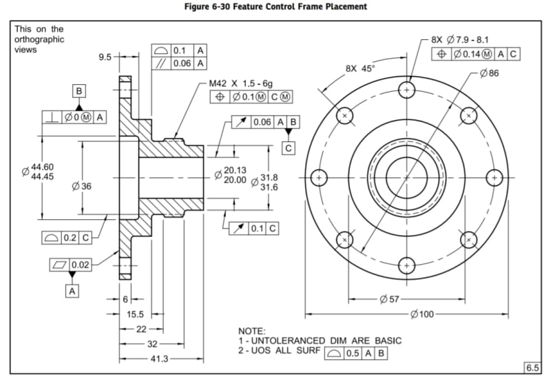
In fig. 6-30, what tolerance controls the length of the threaded M42 section?
There are basic dimensions 22 and 32, however while basic dimension 32 is clearly related to the general profile tolerance since there is a step there that is part of a true profile, I'm not sure what to make of basic dimension 22. It is given to where the basic diameter 36 ends and the thread starts, but is the true profile and the general profile tolerance zone well defined at that place? Part of the problem as I see it is that there is no step there to take part in a clear true profile (basic dia. 36 is only slightly smaller than the minor dia. of M42).
 
Replies continue below

Recommended for you

Could you, please, have a picture attached? Not everyone has access to the document.
 
20211128_145755_o4hkgy.jpg

greenimi, this is the figure.
 
Figures in the standard are incomplete by intent. That portion of the figure and the applicable chamfers are not well defined.
I would read that 10 basic dimension (32-22) is the length of the full formed thread. But it is just me.
To complete a little bit more this figure maybe a note such as "CAD is nominal" or "refer to the CAD model for incomplete definition, basic CAD per model#######" or an equivalent note.

Let me ask a related question: do you think that the general profile is applicable to the 31.6- 31.8 outside diameter?

I think it does. But I am sure it is not clear.
 
greenimi, good point about figures in the standard being generally incomplete, but this specific one - I think that other than the bit about the true profile behavior at the start of the thread (and chamfers as you mentioned), looks to me quite fully defined, isn't it?
Out of curiosity - suppose that the CAD model is not intended to be part of the definition, how would you suggest completing the missing piece?

To your question, I don't think dia. 31.6-31.8 is controlled by the general profile tolerance, as the general tolerance applies only to surfaces the variation of which are not "otherwise specified", whereas the size, form and location of the feature are fully defined by the size and runout tolerances.
 
Burunduk,

Lets ignore the actual thread form for a moment - you're not actually concerned where the thread helix itself starts/ends as the implication as I read it is that the indicated area is fully threaded. Trying to control the start/end of the thread helix itself on features which aren't fully threaded is a bit more difficult and tight control over which requires specialized gauges - its usually best to allow for looser tolerances here when possible (blind tapped holes, screw threads where the shank is not back-cut, etc..) and/or specifications like "min thread depth", "max incomplete thread" or a length where no threads are acceptable.

What you're actually asking is the tolerance on the location of the chamfer of the back cut/tapered portion. A quick scan of some thread standards seems to indicate that the leading/trailing chamfers aren't strictly controlled by your thread definition which makes sense because this can be modified for different purposes even with the same thread form (ie: MAThread or various self-tapping threads though some of these might also have proprietary/custom thread forms). Would you disagree that if a basic (or in your example, either basic or undimensioned) angle is added at each end of the threaded portion that this is fully defined? I'd probably recommend a directly toleranced distance/angle if this location/angle is not extremely critical in most applications though.
 
Burunduk,

As noted above, ASME probably did not care about a complete drawing.

On a real drawing, there should be a note somewhere specifying tolerances for dimensions based on the number of decimals. This would control those tolerances.

Any time I have designed part like this, I specify the distance between the end of the thread and the shoulder. Presumably, I want to screw something down accurately, all the way to the shoulder. I specify the maximum distance. I don't care what the minimum distance is.

I am taking this way too seriously. Greenimi is correct.

--
JHG
 
Thanks for the input, guys.
chez311, I agree that if basic angles are added at both ends of the threaded portion this drawing becomes fully defined, and the length of the threaded portion becomes controlled by the general profile requirement, but I am not sure how inspection-friendly this is. I get why you suggest a directly toleranced distance to one of the ends of the threaded portion. drawoh's suggestion seems to be on the same line.

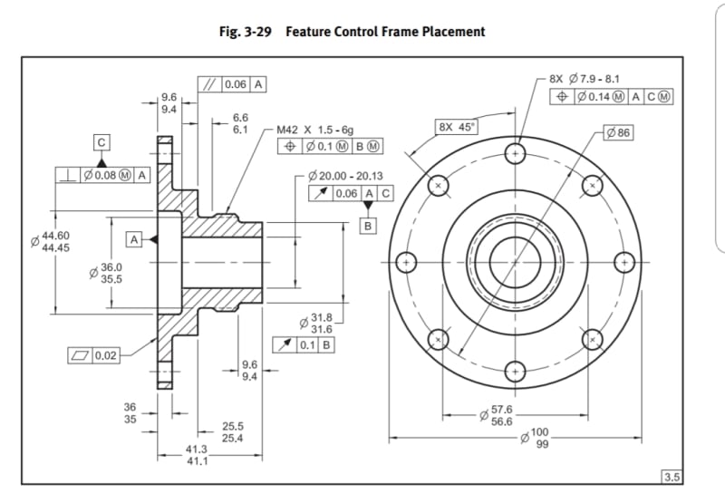
Interestingly,  the version of this figure from the 2009 edition of the standard had all the distances in the axial direction directly toleranced (see the image below). Most of those distances were non-size dimensions. I guess the committee's objective in changing the scheme to basic dimensions and a general profile was to further demonstrate that location dimensions shouldn't be directly toleranced. But would you guys disagree if someone raised a concern that the newer version  of the part design is costlier to inspect (relative to the older one below)?

20211201_051554_zxorfv.jpg
 
Burunduk said:
But would you guys disagree if someone raised a concern that the newer version of the part design is costlier to inspect (relative to the older one below)?
Yes, I would (disagree).
You can measure the applicable profile WITH a caliper, but you would just have more uncertainties, which uncertainty is "un-escapable" -all measurements methods are subject to it (some of them more and some of them less)

 
I agree with greenimi regarding profile vs. directly toleranced dimensions.

Also, I think that addition of basic angles at both ends will be enough only if the drawing is clear that the nominal height of the slopes at the ends is the same.
 
pmarc, greenimi, 
I also think that in most cases, profile of a surface is not the expensive requirement many still consider it to be, and often can be verified with relatively simple metrology equipment. Especially when the tolerance is loose, and the measurement uncertainty is less significant, as in the case of a general profile note.

But (speaking of verifying profile with a caliper...), could the 36 basic diameter in conjunction with the general 0.5 profile tolerance be more stringent than a direct tolerance diameter of 35.75-36.25, because the former requires perfect form at LMC, while the latter does not?

pmarc, I now see how the addition of basic angles at both sides alone does not fully define the geometry. This is how I think that a full definition in the first figure (from the 2018 edition) could be achieved:  The true profile on the left side could be defined by the basic 36 diameter, the basic distance 22 (which is given to the internal theoretical corner), and a basic angle which would be added. On the right side, the true profile is defined by the basic 32 distance locating the step, and the additional thing required would be the chamfer size between the thread and the step. The drawing notes could tell what the unless otherwise specified internal corner radii and external chamfers should be, with a direct tolerance. Does that seem OK?
 
Burunduk,

To answer your first question, it depends on what you mean by more stringent. It is true that the way the 36 diameter has been toleranced in the 2018 figure requires perfect form at LMC, but on the other hand notice that the general profile of 0.5 creates tolerance zone boundaries that are 35.5 and 36.5 in diameter, which means that the size tolerance is doubled compared to the 2009 figure.

Also, I think the change they introduced in 2018 regarding the tolerancing method for the 36 diameter is of different nature than the changes for the axial dimensions. As you pointed out in your initial post, the axial dimensions were changed to support the argument that non-size dimensions should not be directly toleranced. But in case of the diameter, they simply fixed the error made in the 2009 where a geometric tolerance of location was simply missing. And they chose general profile to fix this. So I wouldn't really try to compare the two figures in that aspect.

Regarding the second question, I would probably just add another basic diameter on the right side where the chamfer starts.
 
pmarc, that's a great input.
I suspect that there might be another reason for the basic diameter 36 in the '18 version other than solving the location issue from '09 though. If diameter 36 didn't become basic, they would have another problem with basic dimension 22 and the true profile being well defined. Would you agree?
 
pmarc said:
Yes, I would agree with that.
So a follow up question can be:
If this was a real part and the design department decided to make an update - keep size limits of 35.5-36.5 but also provide a 0.1 position tolerance at MMC, the 2018 version figure would become too stringent (I say that the general tolerance effectively provides zero location error when the AME size of the feature is 36.5). They would probably want to change the diameter to direct tolerance, add the position at MMC requirement, but keep everything else the same. Then they should notice the fact that dimension 22 basic is no longer meaningful (as the intersection it defines misses basic radial location). Would you then recommend changing 22 basic to direct tolerance (despite being a non-size dimension)?
 
I would then change basic 22 to basic 22.x to locate a gage plane on the cone and then apply a basic diameter at that gage plane.
 
pmarc,

Seems very strange to recommend a gage plane on the cone for a chamfer (with its applicable complications such as basic diameter at that gage plane).
I know this is only an academic exercise, but still…..
I am just thinking (from an end user perspective) if I see a chamfer defined with basic angle, basic diameter and basic distance from a datum (granted very robust definition) …well I will just cringe.

But, to your credit, Burunduk asked a theoretical question …and he got a theoretical answer.
Just saying….

 
greenimi,
I am just providing answers to Burunduk's questions within the defined "boundary conditions".

Whether they are academic questions or not is a subjective thing because I might as well ask where, in your opinion, is a border between chamfer and regular cone. Do you know?

Just saying ;-)
 
greenimi, pmarc,
The question may be theoretical, but the dilemma on how to tolerance this kind of features is very real, and one that I face often. I generally hold the opinion that if a feature is non-critical, it should be reflected by a loose tolerance, not a loosely-defined tolerance. On the other hand, to echo greenimi, I don't want the manufacturer to "cringe".
So in case the suggestion about the gage plane was "academic"/"theoretical" would a practical one be different?
 
Burunduk,
I wholeheartedly agree with this approach: "if a feature is non-critical, it should be reflected by a loose tolerance, not a loosely-defined tolerance". Unfortunately, in real-life situations compromises often have to made for different reasons. One of them is cringing manufacturing.

I think the solution that I see most often in similar situations is the 22 dimension directly toleranced and the directly toleranced angle for the slope. Even though both dimensions do not have standard intepretation in Y14.5, that's usually too weak argument to succesfully convince most people to change the scheme to basic dimensions and profile.
 
Status
Not open for further replies.

Part and Inventory Search

Sponsor