Continue to Site

Eng-Tips is the largest engineering community on the Internet

Intelligent Work Forums for Engineering Professionals

  • Congratulations SSS148 on being selected by the Eng-Tips community for having the most helpful posts in the forums last week. Way to Go!

Fig. 8-27 2009 why is Datum B required if it is a valid callout

Status
Not open for further replies.

sendithard

Industrial
Aug 26, 2021
186
I searched the forum on this figure so I'm not trying to create a civil war here ;)

I'm taking this senior exam next week and now that I'm done with reading the standard in detail I'm going over notes.

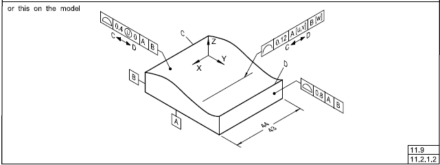
I'm of the opinion you cannot use the fundamental rules for creating a 90deg or zero basic dimension here, b/c of how the rules read..they state you must have basic dimensions listed for the 90deg rule and surface(s) to establish a coincident relationship to establish a zero basic dim.

Anyway, if those basics do exist, then we would not need the datum B for this parallelism callout correct? Since datum B is the viewing direction and line profile is normal/true to said direction I don't see it's requirement.

This is easily answered correctly in an exam, I'm just wondering if there is controversial stuff in the exam like this? Another thing that bothers me is datum shift on a single featue's location. It isn't technically bonus, but b/c it is only one featue, the shift becomes bonus, so if answering a question on what is the additional bonus for a single feature with datum shift would you add the addition datum shift help, or perhaps just list the MMC bonus you get?

Thanks.

 
Replies continue below

Recommended for you

sendithard,

First, for the purposes of the exam I would recommend just memorizing what the standard says about Figure 8-27. It's one of the worst figures for "definition by example" and non-rigorous definition.

The datum B reference does make a difference. It's true that the profile zones are normal to the viewing direction, and the line element orientation is not controlled relative to datum B. The datum B reference sets the orientation of the cutting planes, in which the line elements and tolerance zones are defined. If the sides of the actual part were not perfectly square to each other, establishing the "viewing direction" (and hence the orientation of the cutting planes) would be ambiguous. In other words, when you slice the part you could make the slices parallel to the front or back face, or perpendicular to the left or right face, or some best-fit combination. The datum B reference forces you to make the slices parallel to the back face (i.e. parallel to the plate that the back face is pushed against).

Regarding the last question, datum feature shift doesn't become bonus (even for a single feature). I wouldn't add it to the bonus from the toleranced feature. I believe that Y14.5-1994 had a table with calculations that appeared to do something like that (it was really calculating a maximum possible axis offset, I think), but Y14.5-2009 doesn't have that.

Evan Janeshewski

Axymetrix Quality Engineering Inc.
 
The viewing direction doesn't determine which of the several features nominally parallel to the viewing plane, or any combination of them, would establish the orientation of the tolerance zones, including the possibility that it is some perpendicularity to the end faces or the center plane between the end faces that might be of interest.

The datum shift doesn't often become a similar result to bonus.

For example: three holes in a part and two of them are used as the secondary datum feature reference for the third. If the third hole is between them, it might look like an addition to the bonus, but if the third hole is displaced the additional movement might allow a very large arc of movement that isn't diametral.
 
The below pic is what I think Evan was referring to in his reply. I understand these displacement questions/situations, but they simply follow the idea that datum shift is added to bonus with a single feature.

These displacements questions is what was throwing me off...if you have a single datum feature acting like the primary datum and only one feature located to said datum, you may be able to simply add the datum shift to the bonus, but anywhere otherwise all bets are off. 3D's example of the clocking secondary datum hit home for me.

Capture_s0wq38.jpg
 
That's a fairly useless diagram. But if it's on the test it's the only right way to answer. The displacement can be much larger at installation but it's not to show any practical use.
 
If B is in the line profile FCF to unambiguously orient the cutting planes (and I fully agree this is its role per how Y14.5 sets this up), then is there generally a place for a line profile tolerance that references no datums?
 
pmarc said:
If B is in the line profile FCF to unambiguously orient the cutting planes (and I fully agree this is its role per how Y14.5 sets this up), then is there generally a place for a line profile tolerance that references no datums?

Wouldn't in your datumless profile case, the drafting become specially important and I would say crucial and decisive for the understanding of the drawing?
Maybe this "drafting" deciding factor does not work very well with MBD/MBE trend.

 
This would then be, in my opinion, like saying that drafting matters in one case but not in some other cases. Not sure how about you, but I am not buying this.

And to be clear, I am not saying drafting should matter (MBD is one of the reasons why it shouldn't).
 
pmarc said:
This would then be, in my opinion, like saying that drafting matters in one case but not in some other cases. Not sure how about you, but I am not buying this.

Well, this is what we get from Y14.5, I think.
Until more robust tools are to be provided within ASME (like intersection, orientation, direction, planes) are provided, I guess we will do the best with the current tools (within the existing rules and existing regulations) we currently have.

How do you see your raised issue?


I see it similarly. Additional tools may be needed to address the issue.
 
Hi All,

Figure 11-31 in Y14.5-2018 includes both orthographic views (that has the "view dependent" direction for the line elements) and a model-based view. In the model-based view, the direction of the line elements is defined by an example line element drawn directly on the toleranced surface:

Fig_11-31_Means_This_kb9ep2.png


I'm not sure that this fully defines the direction of the cutting planes and tolerance zones. It's implied that the cutting planes are normal to datum A, but they could also be parallel to datum A. I'm not sure if the direction has something to do with which way the line profile FCF is facing - hopefully not.

Evan Janeshewski

Axymetrix Quality Engineering Inc.
 
Evan,
Shouldn't the profile of a line tolerance zones be on planes normal to the true profile of the feature? My interpretation is that the line elements generated by the normal planes cutting the surface are nominally parallel to both datum A and datum B.
 
Burunduk,

It depends who you ask ;^). This issue is one of the reasons why no mathematical definition was provided for profile of a line in Y14.5.1-2019. There are those who believe that the tolerance zones should be normal to the three-dimensional true profile of the feature. For a feature like the one in Figure 11-31, the zones would be planar but not parallel to each other. For a feature like a tapered airplane wing, the zones would also be nonplanar. I have never been able to make this interpretation work, when applied to an actual part feature. The zones need to move or transform relative to each other in some way, to provide a control that is different from what profile of a surface would provide. I don't see how the nonplanar zones would be able to transform - if they move, they no longer contain their line elements. The only interpretation that I've been able to get to work is that the cutting planes must be parallel to each other, and thus the profile of a line tolerance zones are planar and parallel to each other. There are some committee members that would agree with me, and many that would not ;^).

I agree that the line elements are nominally parallel to both datum A and datum B.

Evan Janeshewski

Axymetrix Quality Engineering Inc.
 
Evan,

"11.3.1 Uniform Tolerance Zone
Profile tolerances apply normal (perpendicular) to the
true profile at all points along the profile"

Let's take a simple cone as an example.
I could use a generous profile of a surface tolerance to control the entire conical surface, and then use a tighter profile of a line tolerance in one or more basically dimensioned locations along the cone to refine the form+size and potentially also location of the circular elements in just those cross-sections. The tolerance zones would be non-planar, but they would still do something different from profile of a surface.
 
Burunduk,

The statement from 11.3.1 has been interpreted in different ways, partly because the definition of a true profile contained hints of both 2D and 3D. Here is a quote from Section 8.2 of Y14.5-2009:

"A profile is an outline of a surface, a shape made up of one or more features, or a two-dimensional element of one or more features."

There is also wording in 8.2.1.2 for Profile of a Line that has been interpreted in different ways:

"Each line element tolerance zone established by the profile of a line tolerance requirement is two-dimensional (an area) and the tolerance zone is normal to the true profile of the feature at each line element."

This wording can be (and has been) interpreted as planar tolerance zones that are normal to each 2D true profile, and as nonplanar tolerance zones that are normal to the 3D true profile.

I understand your example with the conical surface, as refining the form, size, and location at particular cross sections. However, Y14.5 doesn't define profile of a line in this way - it applies to each line element (which means all line elements). Refining the form, size, and location of the cone's circular elements at all cross sections would be equivalent to a profile of a surface. It would be like a set of thin zones that are glued together.

In order to do something different than profile of a surface, we need the profile of a line tolerance zones to move relative to each other in some way. But the standard only says that the zones are normal offsets from the true profile, and doesn't mention that the zones can rotate, translate or progress. It tries to apply the idea of relative translation in very awkward and non-rigorous ways, by overriding the location aspect with a directly toleranced dimension or customized datum reference frame. Further, even if we say that this allows the equivalent of relative translation for each line element, it doesn't work for nonplanar zones. This is because the translation moves the actual line element out of the "curved 2D apace" defined by the tolerance zone. This is very difficult to convey in words, and even in figures (because even 2D sketches don't show the whole picture - it needs to be shown in 3D). It's a real mess.

Evan Janeshewski

Axymetrix Quality Engineering Inc.
 
Evan (emphasis mine said:
"Each line element tolerance zone established by the profile of a line tolerance requirement is two-dimensional (an area) and the tolerance zone is normal to the true profile of the feature at each line element."

This wording can be (and has been) interpreted as planar tolerance zones that are normal to each 2D true profile, and as nonplanar tolerance zones that are normal to the 3D true profile.

Interesting observation between a 2D true profile and a 3D true profile...
Maybe according to the 2009 wording in profile of a line definition, the tolerance zones constructed normal to the 2D true profile are the more workable option, considering that non-planar tolerance zones normal to the 3D true profile (such that could be obtained in a cross-section of a tapered feature) are not really "two-dimensional"?
 
Status
Not open for further replies.

Part and Inventory Search

Sponsor