Continue to Site

Eng-Tips is the largest engineering community on the Internet

Intelligent Work Forums for Engineering Professionals

  • Congratulations KootK on being selected by the Eng-Tips community for having the most helpful posts in the forums last week. Way to Go!

fixing a steel console with only 2 anchors? 3

Status
Not open for further replies.

n3jc

Civil/Environmental
Nov 7, 2016
187
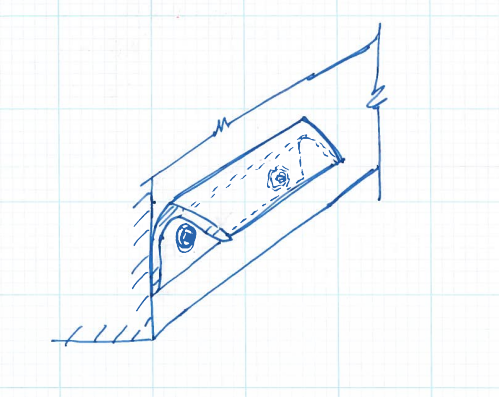
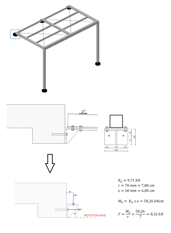
I have to fix a steel console into existing RC beam. Console is supporting a steel canopy beam.
Since RC beam is 250/300 mm I m very limited about how to destribute anchors. I have to consider minimum edge spacing from the edge of concrete and between anchors. So I came up with this:

Normally Id use more than single line of anchors, but in this case forces are small so I think it is OK. Calculations shows that 2 anchors are more than sufficient bu I still feel somewhat uneasy because I have only a single line of anchors. Id add another line but since RC beam is only 300 mm high, I have a problem with steel beam since it shouldnt be too high above the RC beam.

SIDRANJE_gwtnoo.png
 
Replies continue below

Recommended for you

TMH, I don't believe there is any prying action here.

Your sketch implies there is a tension load away from the anchored surface originating between the bolts, but there is none. The tension load is directly at the bolts as a result of the eccentric load.

The deformation shown in your mini-sketch (on the bottom right) cannot occur. The only deformation that can occur is the leg of the angle bending just below the joint between the two legs. If anything the bending in the vertical leg of the angle (especially if the stiffener was not there) would force the steel between the two bolts into the concrete surface, not away from it.

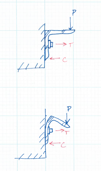
See below. I've removed the stiffener to make it more clear.

anchor1_rfwtkd.png


anchor2_mj6wqr.png
 
I would argue that your sketch is the perfect example of prying action.
 
jayrod,

There is a difference between the tension reaction caused by this scenario and how AISC defines "prying action". While the sketched scenario is "prying" on the bolts, it's not "prying action" as defined by AISC.

"Prying action" is a secondary tension effect cause by plate bending due to a tension load applied directly to the plate element eccentric from a line parallel to and at the centerline of a bolt. See Chapter 9 in the AISC Manual. The scenario we are discussing does not have this tension load and can't have "prying action".
 
Fair enough. However I assume the people here indicating prying are thinking of your sketch.
 
DETstru, I would argue that because the stem is there that it provides a stiff path for a tensile stress component from the flexure of the stem. This tensile stress can cause the typical prying. Obviously there should be some kind of "two-way" action with the compressive stress at the base of the stem but if the plate is thin enough I could definitely see prying action occurring.

I fully agree that the unstiffened angle that you show doesn't receive any prying action, unless the plate was so flexible that it's actually prying the nut itself (but this would have to be a very large deformation I would imagine).

Professional Engineer (ME, NH, MA) Structural Engineer (IL)
American Concrete Industries
 
jayrod said:
I would argue that your sketch is the perfect example of prying action...I assume the people here indicating prying are thinking of your sketch.

I agree. Couldn't have drawn it better myself. In my experience, this is the version of prying action that most folks are concerned with in these situations. The center of compression reaction migrates away from the toe of the angle in a manner that is difficult to predict. This is the version of prying for which I like the stiffener.

TME's version of prying is also legitimate when the stiffnener is in play although I doubt much would come of it for most conventional geometries.

So you've got two kinds of prying potentially. And neither is textbook AISC prying so they're rather difficult to assess. All good reasons to try to detail the issue away as has been suggested several times above.

I like to debate structural engineering theory -- a lot. If I challenge you on something, know that I'm doing so because I respect your opinion enough to either change it or adopt it.
 
TMH,
The horizontal leg of the angle will prevent any meaningful bending that could create "prying action". This situation is similar to the "thick" plates defined in AISC design guide 4 that allow you to ignore "prying action". Once the connecting element is stiff enough, horizontal "prying action" can be ignored.
That's why WT's used to bolt members with tension loads are such a problem, no horizontal leg to stiffen the plate.

Koot,
For the same stiffness reason above, I don't think there is any meaningful two way action. Just the tension load generated from the T/C lever.

jayrod,
Yes they may be thinking that but my original comment was responding to someone saying OP's calc didn't account for prying. I was saying they did account for it. Then the rest of this conversation was based on TMH's next comment specifically about the AISC-defined "prying action"
 
As the leg of the angle deflects, the point load application will move to the left and minimise the e value... the bolt will go into tension...

Dik
 
dik, not sure what you mean. The vertical deflection is negligible (effectively nonexistent with the stiffener) and the bolts are always in tension anyway.
Regardless, that doesn't generate "prying action" since the ledger doesn't bend in the horizontal direction.
 
If there's any deflection... the bolt will go into tension... also deflection will be caused by the point load acting near the end of the beam... it will not occur at the fastener location.

Dik
 
Well, I think we beat that to death, probably best to either make a new topic or move on. For OP's consideration I believe it's safe to say any "prying action" is negligible.

Far more critical is the edge distance.

Professional Engineer (ME, NH, MA) Structural Engineer (IL)
American Concrete Industries
 
Dik, my apologies but I really don't understand what you're getting at.
The bolts are always in tension. I don't think anyone is saying they aren't.
What does the tip deflection have to do with prying action in the horizontal plane??
 
Not saying anything about prying action... (you will have a little of it at both the concrete as well as the steel connection; don't know if it's significant) and, if the bolts were only finger tight, they would tighten a bit due to the deflection of the angle... my thesis is that the point of load application should be closer to the end of the beam... not 60mm from the concrete face...

Dik
 
Ahh ok thanks.
FYI- the bolts can't just be finger tight. They're wedge anchors so without tightening they don't work.

I'm going to stick with my conclusion of no prying action in the horizontal plane because of the stiffness of the angle in that plane. The only forces on these bolts are shear and tension from the eccentric load (via T/C lever arm). No secondary "prying action."
 
sorry... should have clarified it... the bolts securing the steel...

Dik
 
I have read through this thread several times now. TNX everyone for contribution/replies.

What I still dont understand is: why is there so much talking about value e - distance from beam action on angle to edge of the RC beam? As far as I know If I choose larger value of e, the larger eccentricity is which means larger moment and larger tension forces in bolts... So why so much talk about e being closer to the RC beam? e being larger means being more conservative - being on the safe side right?
I use e as a distance between half of a contact surface between a steel beam and steel angle and edge of RC beam
 
Oh, I was suggesting to use an e at the end of the bracket to be conservative but and e to the middle of the bearing surface would also be reasonable. You are correct that a smaller eccentricity is less conservative.

Professional Engineer (ME, NH, MA) Structural Engineer (IL)
American Concrete Industries
 
With the stiffener in there, I favour at least a triangular distribution increasing away from the heel. Point load at the end probably isn't too far off reality.

I like to debate structural engineering theory -- a lot. If I challenge you on something, know that I'm doing so because I respect your opinion enough to either change it or adopt it.
 
Thanks for replies. I agree.

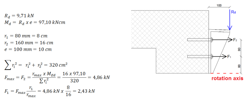
I want to ask another question in a case of 2 lines of bolts as shown below.

What is your opinion about lever arm r1 = 80 mm and r2 =80 + 80 = 160 mm.
Would you consider rotation at the bottom of RC beam or higher? What if there was no stiffener but just an angle? would you consider the same? I think it all depends on plate thickness of steel angle.


pr2_bdvk5r.png
 
I think that's fairly rational with one exception: you keep showing the point of rotation as being at the very bottom of the bracket. I feel that there needs to be some acknowledgement of the fact that the compressive stress block against the beam takes up some finite amount of space which will reduce your effective lever arm.

For small scale applications like this, I'll assume the point of rotation (neutral axis) to be right at the upper anchor with a triangular compression stress block projecting downwards. That's a physical impossibility, of course, but I feel that it's nicely conservative and it takes me five minutes. In that case, I'll either ignore the lower anchors or assume that they only participate in shear.

In all the hubbabaloo over the taxonomy of the particular kind of prying action we have here, I fear that we may have lost sight of what is some very wise and time honored wisdom: turn the angle leg upwards if you can, as others have recommended above. Do that because:

1) It greatly reduces the need for the stiffener.
2) It moves your anchors to a more favorable location for shear breakout, probably eliminating the need for two rows.
3) It keeps your center of concrete compression pretty reliably near the angle heel reducing that source of non-AISC "prying".
4) It eliminates the non-AISC prying associated with the heel of the angle drifting over laterally (P-delta effectively).

These are all good things when it comes to developing a simple, reliable connection.


I like to debate structural engineering theory -- a lot. If I challenge you on something, know that I'm doing so because I respect your opinion enough to either change it or adopt it.
 
Status
Not open for further replies.

Part and Inventory Search

Sponsor