Eng-Tips is the largest engineering community on the Internet

Intelligent Work Forums for Engineering Professionals

Flat-Face to Ring-Joint flange mating 2

Status
Not open for further replies.

TylerM

Mechanical
Feb 16, 2017
32
0
0
US
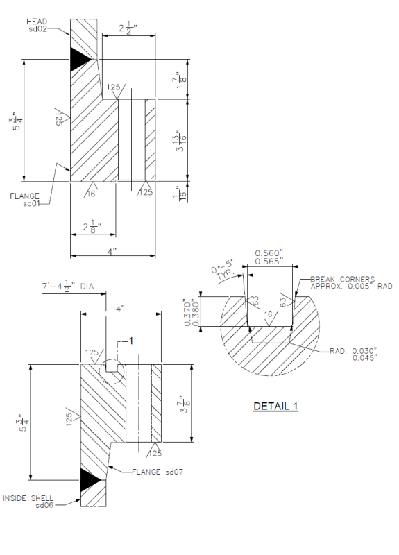
I have a flange I’m looking at and the top half of it is a flat face flange while the bottom half is a ring joint flange (ring depth is 0.3”). The type of gasket the engineer is using is an elastomer with less than 75A shore Durometer with dimensions of: Gasket height=1.0” Gasket thickness=0.5” (So it’s taller than it is thick, much like a ring joint gasket). He’s designing it for the rubber-like gasket to go into the ring joint 0.3” then crush roughly the other 0.7”. Note that this is only a 300 psi system and operates at room temperature.

Has anyone in all their years of experience seen something like this? Secondly, has anyone seen a flange configuration like this before Flat-to-ring joint?
 
Replies continue below

Recommended for you

Untitled_r2fboc.png


These are the two cross sections for the flange described above.
 
Nope,

Never seen anything like this before.

Any idea why your colleague has decided to reinvent the wheel?

I guess in the end it's essentially a form of flat face flange joint with a strange gasket.

I personally would have put the groove to hold the gasket more central on the face as I think it will just ooze into the bolt holes and you'll have a much thinner gasket section by the bolt holes than elsewhere.

300 psi isn't to be sniffed at when it's a jet of liquid or gas coming at you out of a flange.

Remember - More details = better answers
Also: If you get a response it's polite to respond to it.
 
Well, it is a 7 ft-4" diameter, so you are well past "conventional" pipe-face-sized components. But the warning about the very small distance between the outside of the O-ring ??? groove and bolt holes is very important.

Using existing O-ring technology and methods and manufacturers and suppliers are more relevant than extrapolating a pipe face ring joint sized up to that diameter.
 
This isn't actually an appendix Y flange, it has a raised face so would perform quite poorly with an o-ring. If an o-ring was used you would want minimal rotation so a flat faced flange would be essential.

Regarding the proposed gasket, crushing the gasket will destroy any elastic recovery and the joint will struggle to maintain a seal. The amount of compression on a rubber gasket is critical when considering permanent set, relaxation and joint movement. The permissible amount of compression is actually quite small.

For rotation the groove is better near the bolts but assuming you can eliminate all rotation (as required for an o-ring - assuming you choose that option), then close to the bore of the flange will minimize the pressure area.

Either change it to a kammprofile or ring gasket (or other suitable type) with raised faces or design properly for an o-ring. However, the o-ring will require relatively tight tolerances which could be difficult over this diameter.
 
Agree w/ marty007. Self-Energizing gasket...

On Edit: And yes, note BJI's caution on tolerances.

The problem with sloppy work is that the supply FAR EXCEEDS the demand
 
The kammpro adapter can't be fitted to this joint since it isn't a real RTJ groove, 0-5 deg angle vs. 23 deg required for RTJ. The current groove is more akin to an o-ring groove but would be better with no taper, or possibly a slight negative taper (but based on the proposed gasket in the OP, there is likely no sound basis for the current geometry). The description seemed to indicate a new design so a better gasket could be selected without resorting to a conversion / adapter gasket IMO.
 
I'd missed the 7 foot diameter bit...

Still not sure why you can't use an existing system

Remember - More details = better answers
Also: If you get a response it's polite to respond to it.
 
I would say the intent of the designer was for an O-ring, not a 1" tall x 0.3" wide ring - note that rubber is incompressible, so your proposal has around 40% more rubber than groove, so what happens to the over-spill?... I'd say the design is for an 88.3/4" x 7/16" section O-ring (hence around 15-20% compression on section and around 75% fill of groove, with the seal tight on O/D which is common.
You have not given the other details for the flange, but if the back width is only 2.1/2" then the bolts are presumably only 1", diameter. Thus, whilst an O-ring is pressure energised, then just to cater for the pressure forces alone you will need quite a lot of them e.g. compare this to other similar large flanges like AWWA or Taylor-Forge at this diameter in terms of number and size of bolt. The O-ring groove also should sit well inside the r.f. so any bolt hole misalignment on assembly does not lead to any extrusion gaps.
 
Thank you everyone for your thoughtful and insightful replies.
I assume the engineer was designing the flange to be an O-ring type instead of using a 1” x 0.5” x 87.75”OD gasket, that was he wouldn’t have an extreme amount of over-spill.

KevinNZ, it is a full penetration weld, it just has a ¼” root pass.
gasketguru, the flange is held together with one hundred and eight 1.125” diameter bolts.
 
That makes sense, as of course the hydrostatic force as seal diameter x 300 psi then equates to just under 25 ksi bolt stress - a typical value for B7 etc. - the space is slightly tight as a 1.1/8" usually has 1.5" from hub to PCD and 1.125 from PCD to O/D so 2.5/8" compared to 2.1/2", to allow space for washers, spanners etc.
One additional thought - I assume the flange face is horizontal so you can simply lay the O-ring in the groove, but if the flange face is vertical, then you might get your seal supplier to look at an extruded and mould joined 7/16" "D" seal (e.g. round top and flat base) - that way a few dabs of adhesive can often be used to help hold it in place for installation - you still get about 80% fill of groove max, so no overfill.
 
gasketguru, thanks for the tip.

How would I go about preform calculations per ASME BPVC Div. 1? I assume I would use Mandatory Appendix 2, but what b[sub]o[/sub] value [basic gasket seating width (from Table 2-5.2)] would I use?
 
Surely if it is a pressure energised rubber O-ring then for traditional Taylor-Forge / ASME VIII calcs., then m and y are both zero (previous table - 2.5.1), so from the various parts of the load calcs, then what you are left with is the hydrostatic force as pi/4 x G^2 x p which is the pressure x area at the pitch diameter of the O-ring, used for Ht in the moment calcs etc.
 
gasketguru, Thanks for your reply. You are correct, because it's self energising every equation that b[sub]o[/sub] is used in equals zero and the effect doesn't carry on in the later equations.

Thanks again everyone for your insite.
 
Status
Not open for further replies.
Back
Top