Continue to Site

Eng-Tips is the largest engineering community on the Internet

Intelligent Work Forums for Engineering Professionals

  • Congratulations SSS148 on being selected by the Eng-Tips community for having the most helpful posts in the forums last week. Way to Go!

Flatness strange question 2

Status
Not open for further replies.

sendithard

Industrial
Aug 26, 2021
186
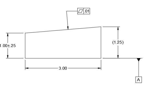
EDIT: the below drawing is representing the final machined part, a perfect part would be a perfectly square 1-2-3 block, datum a just represents the surface plate method.

I'm learning the CMM now and the GDT is really hitting home now, thanks for all your help in the past.. I get tripped up from time to time and the below issue is really bothering me.

Flatness....I was taught manual inspection on a surface plate. If we inspect a 1-2-3 block, you place it on the surface plate(datum A touches the plate) and run a dial indicator over the top surface. The dial min vs max is your flatness amount.

Now my mind wonders why the above method is wrong...if someone machines a part with a top surface so bad that it maximizes the plus/minus height tolerance, but the top has a nearly perfectly ground surface, you have a part that is bad, but within the plus/minus height tolerance...and is well within a flatness tolerance due to it being almost a ground like surface quality. BUT if I check flatness on the top feature by placing the bottom on the surface plate, I am going to get a massive 0.25 variance on the min max dial indicator. What is the appropriate way to measure flatness outside the CMM and on a surface plate? Am I confused?

Capture_p26qu1.jpg
 
Replies continue below

Recommended for you

sendithard,

The manual inspection method you described would be correct for Parallelism, not Flatness. For Flatness, you don't need to align the bottom surface of the part to the plate. You can level the part to get the best possible indicator reading on the top surface (adjustable jacking screws are often used).

Evan Janeshewski

Axymetrix Quality Engineering Inc.
 
Put that face on the surface plate and find the maximum feeler gauge that will fit in the gap; start with a 0.01 and if it won't fit then it meets the requirement.
 
Thanks to both of you.

3DDave, what you said made some much simple sense I feel as dumb as you can feel without caring that I feel dumb. Thanks, cleared me all up. You all are an awesome resource I can't say thanks enough.
 
Hey 3DDave,

I've asked several manual inspection questions and you seen quite keen on the exact ways to approach the measurement. Do you mind sharing what your experience is in manual and how/if it relates to what you have seen in cmm? Not looking for an essay, just your thoughts however long they are I'll read em all.
 
The feeler gauge method won't work if the inspected face is concave and the concavity is greater rhan .01.
 
That's a really atypical case. But an inspector would see that before putting it on the surface plate and note where that deviation was to add it to any gap. It's really that simple.

If they really care they can take a dial indicator and put the indicator through a hole in a flat plate and move the part so the indicator can check those as well.
 
I don't think that the concave surface scenario would be atypical, therefore the dial indicator method would work much better.
 
Sendithard... You could perhaps do some initial set-up work to level that top surface first(use little gage blocks to jack up it up here or there), and then once you factor out any parallelism error you could use a dial indicator to run across that top surface.
But even better is the method mentioned above with a dial indicator mounted through a little hole in the inspection plate; then your part would be flipped upside-down so that the surface in question sits directly on the table. See the attached graphic for a crude image of this idea.
 
 https://files.engineering.com/getfile.aspx?folder=6c73e8d7-eeef-4cd8-bb58-c1cf9f586b7b&file=DialInd.png
The image of a surface plate with a hole is typically shown in GD&T textbooks. I though it was just to help grasp the concept of flatness verification and rarely used in the real world.
But many seem to say that the method is actually commonly used. Is it true?
I would appreciate if by any chance someone could show a picture of actual full inspection setup.
 
We specify many parts with very tight flatness requirements (sub micron). We always inspect with a profilometer that traces the part surface. The software will level the trace to take out any tilt. You could never check this with a surface plate or even a CMM. You could use an optical flat but they are small parts so that becomes difficult.

----------------------------------------

The Help for this program was created in Windows Help format, which depends on a feature that isn't included in this version of Windows.
 
So it will maybe find the high points and make a plane and measure the worst points from that?
 
Status
Not open for further replies.

Part and Inventory Search

Sponsor