Eng-Tips is the largest engineering community on the Internet

Intelligent Work Forums for Engineering Professionals

Flexural Strength of a Steel Plate 2

Status
Not open for further replies.

gmoney731

Structural
Oct 24, 2018
32
0
0
US
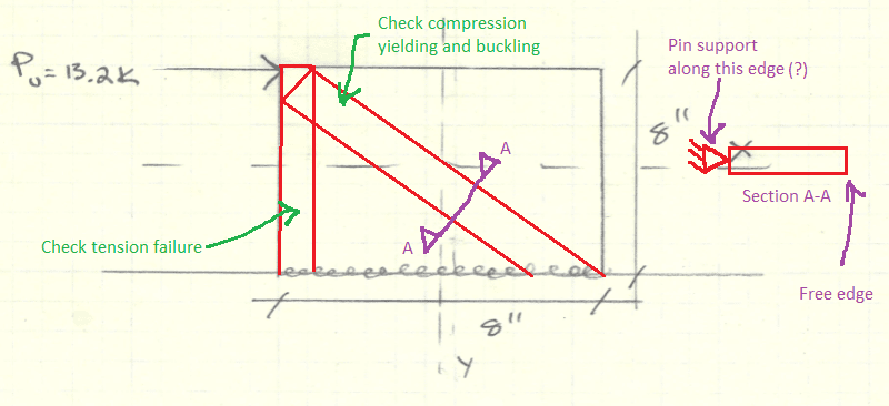
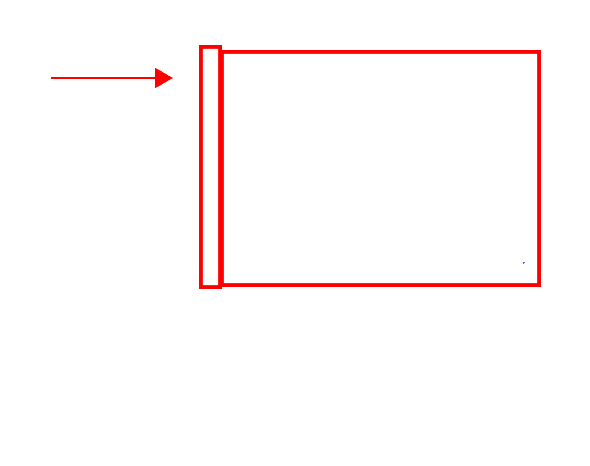
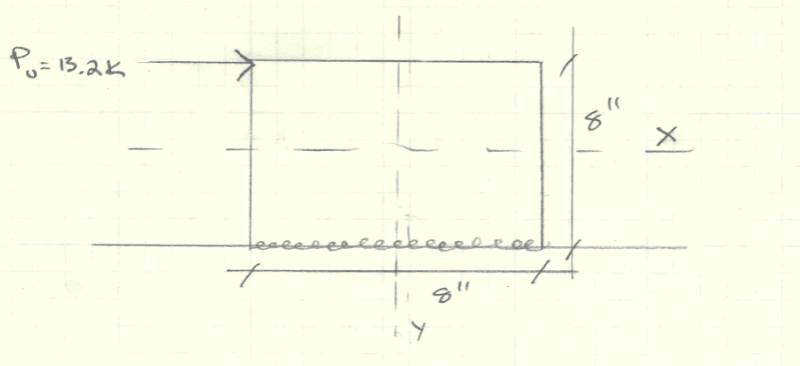
I have a 1/2" cantilevered steel plate welded to a steel beam. The plate is experiencing a 13 kip load as shown in the image below:

case_biz67e.png


My question is, can I use AISC 14th F11. RECTANGULAR BARS AND ROUNDS and apply those equations to calculate flexural strength? My understanding was that bars are different than plates, even though they both have rectangular sections.

Can anyone provide structural theory that can justify it? I have seen some explanations on here talking about the Z/S ratio.

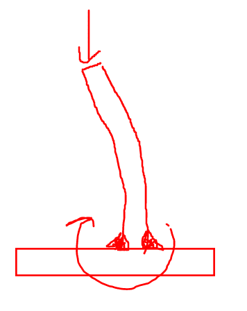
At work, I am being told to just check (phi)Mn = Fy*S, and I also want to know whether it is reasonable to assume that the plate can get to the plastic moment without buckling or other modes of failure?
 
Replies continue below

Recommended for you

I'd run it first using F11, but I'd set your unbraced length at 16". See how much of a hit you'd take to the nominal bending strength.

The more I look at it, the more it looks like a stiffened seated connection (but rotated 90 degrees). If someone in your office has a Salmon and Johnson steel design textbook, they have a procedure for designing that stiffener.
 
Thanks, winelandv. This is actually a "stop plate" that is welded to a crane runway beam, as a means to stop a bridge crane at one end of the runway while it is in motion.

The force is the longitudinal force from the crane. I don't think the plate needs to be 8" tall, but as of now, if I perform the following check per AISC F11:

(Lb)*(d)/(t^2) <= 0.08*(E)/Fy?

Lb = 2*8" (cantilever) = 16"
d = 8"
t = 3/4" (I know I said 1/2" in original post, I was mistaken)
E = 29,000 ksi
Fy = 36 ksi (A36 steel)

The problem is I am getting 227.5 on the left vs 64.4 on the right

So I fail this check for "bars" bent about the major axis...meaning I can't apply F11 to this?

I wonder why AISC does not have any direct specifications for plates in the Design Chapters?
 
You can still apply F11. You need to turn the page to F11.2.(b). It gives you another check to see if your ratio is below 1.9*E/Fy. It also includes Mn for your plate being in this region.

Finally, F11.2.(c) has the Mn equation for when your ratio is larger than the 1.9*E/Fy.
 
gmoney731 said:
My understanding was that bars are different than plates, even though they both have rectangular sections.
There is no structural difference between bars and plates. The only distinction between them is that bars are fabricated from flat stock that is 8" wide or less, while plate stock is wider. But for design, the steel member doesn't know whether it was fabricated from bar stock or plate stock. So for practical purposes on drawings, most engineers just call both items "plates" on their drawings and don't dictate to the contractor/fabricator which type of stock must be used.
 
13 kip = 57 kN (according to a quick google search; correct me if I am wrong)

This is a significant load. With given dimensions (approx 200mm x 200mm x 25mm in SI units), it may or may not resist the load without buckling or locally yielding. Furthermore, if the crane has any significant speed (say, a few meters per second) and a significant mass (probable) when impacting, the load should be calculated with a dynamic analysis. How did you determine that load? Make sure that the load is conservatively estimated.

An option is to model the plate as a membrane (thin slab, taking only in-plane forces), apply the load and rigid connection, and check if the von Mises stress exceeds yield. Then, a buckling check (eigenvalue buckling analysis) can be done as a check for stability.

If you want to model it by hand, you may use linear thin slab elements (triangles, 2 or 4 elements), hand-calculate the element stiffnesses and nodal load, apply boundary conditions (zero displacement at nodes along clamped edge) and solve the system for nodal displacements. Then, use the interpolation inside the element to compute in-plane forces and stresses. Thus will take some time, and is just a more error-prone version of the computer analysis, which you no doubt have access to.

Using the beam simplification will incur significant modelling error, since it amounts to idealizing the plate as a cantilever, but it may be used to double-check the FEA results.

EDIT: to clarify, the other modes of failure include at least shear buckling, compression buckling, local yielding and crushing. Furthermore, plastic sectional capacity is unlikely to be achieved, and thus the elastic section modulus would be the "conservative" (if other modelling errors are ignored) choice for estimating strength of the plate as if it were a beam.
 
Another note on the design: it would be better to place the stop plate in such a way that the load is distributed along the entire left edge, converting the 13 kip point load into a line load. This would reduce stresses in the plate, reduce the buckling load and reduce the extent of/risk of local yielding and crushing of the plate edge.
 
For design procedure....

Your extended plate looks just like an extended shear tab connection. You just don't have the bolt holes and your eccentricity is a little larger.

I'm 99% sure there are design examples of this that go through all the limit states in the AISC Design Examples.
 
Gmoney731:
What’s the dia. of your wheels? Aren’t those wheel stops usually contoured to match the wheel shape/dia.? You don’t want the wheel hitting on a sharp top corner of that stop pl., that could damage the wheel over time. And, at the same time the pl. should be high enough so the wheel can not climb it on contact. You do not want the wheel flanges disengaging the rail. I’d have the front edge of that 8" high pl. be vert. for 1" to 1.5" high, then contoured so the wheel hit it over some edge length/height at about 4" high. An inch or so either side of that 4" high elev. the wheel and the pl. contours actually match, then there is some slight clearance above and below this area. Then on that leading edge, and on the sides of the bot. edge, I’d grind 1/4 or 5/16" x 3" long bevels; fill those bevels with weld, then put a fillet weld over the bevel and all around the pl., to the rail. Don’t leave any notches, undercuts or craters in the welds or pl. in th front edge region. Otherwise, your problem is primarily a shear and potential pl. buckling problem. That front weld is designed for (13.2k)(4" + 1" ht., whl. contact ht.)/(8" base length - 1" ea. end or abt. 6" base lever arm) = 11k of upward force on the front of that weld. Then the reinforcing fillet all around takes the 13.2k shear to the rail.
 
We normally weld a bit of beam off cut or similar above the beam, often the crane support beams are not stock length so we us the offcuts. as dhengr has indicated, a single flat would cause issues if the bump was engaged with the wheel.
 
Look at Shakya & Vinnakota, AISC Engineering Journal Q3 2008. They worked out an efficient approach to triangular gusset design by looking at them as a series of columns that get shorter and shorter. Then they integrated across the height of the triangle to sum the capacities.
 
Not saying I would do it this way, but what about a steel strut-and-tie model?

I imagine this approach would be lower-bound (same as for concrete), but maybe I'm wrong.

Untitled_zfftjx.png
 
gusmurr,

That approach (strut-and-tie) is always an upper-bound method (not necessarily conservative), since it involves approximating a kinematic mechanism (failure mode), and the accuracy of the solution depends on how close the solution is to the actual collapse mechanism. A simple way to put it: assuming some plastic failure mechanism will invariably overestimate the stiffness of the member (a plate in this case), which will underestimate the displacement field and therefore underestimate the internal forces involved in an average sense across the plate domain.
 
winelandv said:
The more I look at it, the more it looks like a stiffened seated connection (but rotated 90 degrees).

That's the treatment that I would go with whether it's:

1) Salmon & Johnson.
2) Vinnakota which I've not yet tried.
3) Strut and tie which I've done on many occasions.

All of those work for me. I don't favor the F11 approach because, in my mind, F11 is for beams having a span to depth ratio that implies Bernoulli flexure. At 8" x 8", this is definitely not Bernoulli flexure.

Also like the stiffened seat approach, I would toss in a perpendicular plate as shown below if that would be spatially acceptable. This will stabilize your system at the point of load application which is structural stability gold. Yeah, there's still a buckling concern in the plate parallel to load but at least that's a pin-pin system. Without the perpendicular plate, your stability relies on the parallel plate cantilevering up from it's fillet welds which is a bit icky in my opinion.

C01_q9nnsh.png
 
gusmurr said:
Not saying I would do it this way, but what about a steel strut-and-tie model?

I've done that a number of times and support the approach. Yeah, it's lower bound. However, if one uses reasonable proportions for the strut and tie and ignores most of the bounded plate area, as you have, it's hard to imagine going too far wrong with that.
 
With regard to the unstiffened plate stability, I've also been wondering how legitimate it is to use paired fillet weld in bending as shown below. I'm sure that it has some bending capacity but it strikes me as a little sketchy just the same. This paper, which I sadly do not have, seems to suggest that the right combination of fillet welds could "develop" the plate in this way for seismic applications. That's obviously encouraging.

C01_so7zjh.png
 
JoelTXCive said:
Your extended plate looks just like an extended shear tab connection. You just don't have the bolt holes and your eccentricity is a little larger.

I had that same thought. And that method may well be appropriate. There were, however, two stability differences between the shear tab and OP's condition that gave me pause:

1) The shear tab is uniformly loaded in shear which is a more stable condition than is OP's front loading.

2) Do extended shear tabs rotationally stabilize their supported beams? Or do supported beams rotationally stabilize the shear tabs which are designed to go plastic in flexure? I don't actually know the answer that but, if it's the latter, then that would negatively impact the stability of OP's situation.
 
Status
Not open for further replies.
Back
Top