Continue to Site

Eng-Tips is the largest engineering community on the Internet

Intelligent Work Forums for Engineering Professionals

  • Congratulations KootK on being selected by the Eng-Tips community for having the most helpful posts in the forums last week. Way to Go!

Flexural Strength of a Steel Plate 2

Status
Not open for further replies.

gmoney731

Structural
Oct 24, 2018
32
I have a 1/2" cantilevered steel plate welded to a steel beam. The plate is experiencing a 13 kip load as shown in the image below:
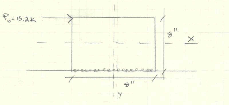
case_biz67e.png


My question is, can I use AISC 14th F11. RECTANGULAR BARS AND ROUNDS and apply those equations to calculate flexural strength? My understanding was that bars are different than plates, even though they both have rectangular sections.

Can anyone provide structural theory that can justify it? I have seen some explanations on here talking about the Z/S ratio.

At work, I am being told to just check (phi)Mn = Fy*S, and I also want to know whether it is reasonable to assume that the plate can get to the plastic moment without buckling or other modes of failure?
 
Replies continue below

Recommended for you

To provide a flavor for the Vinnakota design aid...

C01_j0dmlt.png


C01_etzyzg.png


C01_iad1c9.png


C01_cl2hfy.png
 
centondollar, KootK,

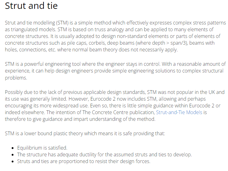
Thanks for the responses. It seems you both have different opinions on whether that approach would be lower- or upper-bound. I agree with centondollar that traditional yield line analysis is always upper-bound. And we know that a concrete S&T model is always lower-bound. But a steel strut-and-tie model? In my mind it should be lower-bound but I can't really explain why.

KootK, do you have any references or could point me in the right direction regarding steel S&T models?

Thanks
 
KootK,

KootK said:
With regard to the unstiffened plate stability, I've also been wondering how legitimate it is to use paired fillet weld in bending as shown below. I'm sure that it has some bending capacity but it strikes me as a little sketchy just the same.

In Padeye design, it is standard to use those fillets to resist any out of plane bending that the padeye sees. Granted, the padeye assembly has a tension force, but I don't see why those fillets couldn't do the same for a compressive load. Unlike a padeye, we're loading the top at one end (instead of the middle), so the question would be, how much of the plate (and by extension, the fillet welds) could we assume to engage for stability, and then is that stiff enough. My hunch would be that you would need to thicken the plate to get acceptable stiffness to stabilize the plate.

At any rate, I think our OP should slap the perpendicular plate on this assembly, do the stiffened seat, and move on to the next challenge.
 
gusmurr said:
KootK, do you have any references or could point me in the right direction regarding steel S&T models?

Every steel truss that's ever been designed is a lower bound, steel, strut and tie model.
 
windlandv said:
In Padeye design, it is standard to use those fillets to resist any out of plane bending that the padeye sees.

That helps alleviate my concern. I'll take it, thanks.
 
"And we know that a concrete S&T model is always lower-bound. But a steel strut-and-tie model? In my mind it should be lower-bound but I can't really explain why."
Concrete strut-and-tie models are upper bound solutions in practice, since they are based on assuming some stress distribution (which is analogous to assuming locations of plastic hinges and the failure mechanism) which may or may not be decided using elastic solutions as reference, and then solving the model. If the stress field is reasonably well known beforehand, and the struts and ties are located accordingly, the error may be acceptably small.

STM is different from the normal member design philosophy, in which an equilibrium configuration is found (by e.g. beam theory) and the section is designed by assuming plastic cross-sectional behavior; then, the cross-sectional resistance is always larger than the internal forces generated by the (equilibrated) external forces. In STM, the equilibrium configuration is not straightforward, and thus the orientation and placement of struts, ties and nodes is also not straightforward, and thus the error is not readily measurable.

In my opinion, it will be easier to perform an elastic membrane analysis than to find an accurate STM model for this case.
 
KootK:
"Every steel truss that's ever been designed is a lower bound, steel, strut and tie model. "

Steel trusses are designed by applying elastic theory and (if done by hand) a dimension reduction model that reduces members into bars. There is no guesswork involved, unlike in the STM, in which the structural resistance is idealized by assuming discrete bar-type resistance for a structural member that in reality is exposed to a more complicated stress field. Real structures (trusses and rods not included) are not collections of struts and ties, and the attempt to model them as such is not necessarily a conservative solution.
 
KootK said:
Do extended shear tabs rotationally stabilize their supported beams? Or do supported beams rotationally stabilize the shear tabs which are designed to go plastic in flexure?

The section that details the buckling check for shear tabs in the Steel Construction Manual says, "This check assumes that beam is supported near the end of the plate...", so they are assuming that the beam helps prevent rotation. This means that the cantilever steel plate does not meet the fundamental assumption used for the shear tab buckling check.

However, the way that the buckling check for shear tabs works is that you use the double-coped beam procedure. This procedure has you calculate a Cb value that is at least greater than 1.84, and then use it in the section F11 check. This supports the idea that the F11 check would be valid to use, but I would be using a Cb value of 1.0 and would also likely double the unbraced length since the load is being applied above the shear center.

I would also still include the combined shear and flexure yielding check that is recommended for shear tabs (Equation 10-5):
(Vu/ΦVn)² + (Mu/ΦMn)² ≤ 1.0​

Structural Engineering Software: Structural Engineering Videos:
 
centondollar said:
Concrete strut-and-tie models are upper bound solutions in practice...

I disagree with you utterly on that, as does every reference on strut and tie design that I've ever encountered, including the fourth paragraph of this one: Link. However, from recent experience on this thread, I know that you hold your opinion on this matter very strongly even though no one here or in the world at large seems to share that opinion. And that's okay since there's something to be said for being a rebel and trusting your own instincts.

Still, I've no interest in wasting my own time in trying persuade the unpersuadable. So, by and large, I'd like to just leave you to your opinion if you'll allow it. I will, however, attempt to answer gusmurr's question with respect to just what it is that makes yield line upper bound and STM lower bound. If you have something new and interesting (rather than old and repetitive) to share in response to that, I'll be grateful to hear about it.

C01_e6nvgp.png
 
The engineer is mostly in control of his or her own audacity and fearlessness when it comes to STM.

As I´ve mentioned previously, equilibrium is by definition not satisfied in a strut-and-tie model, since the continuous domain (for which some elastic solution is often available) is discretized (often very roughly) into bars. Concrete plates and beams are not collections of trusses, and modelling them as trusses will not necessarily capture a sufficient amount of the equilibrium solution (e.g., elastic 2D solution), even though such models may be useful! In short, the STM is not foolproof, unlike e.g., ordinary RC beam design in which equilibrium is used to derive design forces and the plastic section design ensures capacity against such equilibrium.

Choose the truss model poorly, and the STM design will fall short and fail.

PS. There is no tool for an ordinary engineer to estimate the ductility of a corbel, deep beam, pile cap or other complicated structure with such accuracy that a method warrants the word "safe".
 
gusmurr said:
But a steel strut-and-tie model? In my mind it should be lower-bound but I can't really explain why.

I see it like this.

PLATE DESIGN WITH THE YIELD LINE METHOD

When you employ the yield line method in practice to plate elements, you're usually using the "work method" which is based on virtual work and energy balance. If you conduct a close examination of the individual panels between your work lines, you will find that they are almost never in perfect equilibrium. This is primarily what makes the method an upper bound method. Two of the available methods for dealing with that imperfect equilibrium include:

1) Most commonly, if you're reasonably close to being in equilibrium, you just add 10% to your design moments and move on. You know, "engineering".

2) Less commonly, you can utilize an alternate method known as the "equilibrium method". As the name implies, this method does enforce equilibrium. It does that by introducing nodal loads on your panels to get the job done. This method is computationally inefficient so, when it is used, it's usually used as a way of guiding the practitioner in the modification of her work method model towards one closer to the true, equilibrium solution.

MEMBER DESIGN WITH THE STRUT AND TIE METHOD

When you design with the strut and tie method, you model your system as a determinate truss within the confines of the real, physical structure. By definition, a properly analyzed, determinate truss is in equilibrium with the external loads applied to it. So you have a complete load path from the start that does satisfy equilibrium and the "design" is reduced to simply checking the capacity of the parts and pieces. This is why the strut and tie method is a lower bound method.

Selecting a strut and tie method that satisfies equilibrium is comically simple. Truly, any determinate truss arrangement will do from an ultimate limit state perspective so long as the system possess enough ductility to transition from its elastic state of stress to the plastic stress field assumed by the strut and tie model without being torn apart. That said, good strut and tie models do closely align with elastic stress fields. The reasons for that are primarily:

1) Such a model will require less ductility to transition successfully from the elastic state of stress to the plastic one and;

2) Such a model will tend to deflect less.
 
ProgrammingPE said:
The section that details the buckling check for shear tabs in the Steel Construction Manual says, "This check assumes that beam is supported near the end of the plate...", so they are assuming that the beam helps prevent rotation. This means that the cantilever steel plate does not meet the fundamental assumption used for the shear tab buckling check.

Thanks for that. I'd feared that might be the case. It's a bit disconcerting in that often, when I see the extended shear tab connection used, the separate rotational restrain mechanism is not present.

ProgrammingPE said:
However, the way that the buckling check for shear tabs works is that you use the double-coped beam procedure. This procedure has you calculate a Cb value that is at least greater than 1.84, and then use it in the section F11 check. This supports the idea that the F11 check would be valid to use, but I would be using a Cb value of 1.0 and would also likely double the unbraced length since the load is being applied above the shear center.

I see what you mean. It seems that you'd have to quadruple your unbraced length, however, given that the double coped procedure is predicated upon a pin-pin-ish buckling mode as shown below (from the Dowswell work) rather than a cantilevered model as we have here.

C01_g7ebda.png
 
Interesting thoughts, KootK. Just a few notes:

The strut and tie method involves approximating a stress field with discrete truss elements. This means, in practice, that the load path is not "complete" - it is roughly approximated. Analogously, the displacement method (FEA) underestimates energy, overestimates stiffness and is thus an upper-bound method for which the solution converges (under certain conditions) when the discretization and/or element type is improved. Converging a STM model is, however, not as straightforward as converging a finite element solution.

Regarding selection of STM, it is not comically simple. The reason? Precisely what you point out: ductility is not an easily measurable quality (for RC, steel or any other material). Another reason for the difficulty in finding a proper STM model is the fact that a deep beam, corbel or pile cap is not actually a collection of struts and ties: those are only extremely idealized models that are accurate for certain materials (e.g., steel) under some restricted set of loadings.

If STM were as simple as you would like to believe, it would not be the bane of every standard writer and reinforced concrete design society, authority and researcher. It is more of an art than a science, for the reasons I have laid out in this post, and the literature will support this claim.

As a side note, the modified compression field theory (MCFT) was introduced some 30 years ago for predicting shear resistance in deep beams and thin wall slabs precisely due to the inadequacy of the STM model (currently applied in the Eurocodes) for predicting shear capacity; at large load levels (including transverse compression loading) for deep members, the STM formulas grossly overestimate the capacity. AASHTO has caught up to the development of RC shear design methods and now presents MCFT as the preferred design method for shear in RC bridge girders. The lesson: STM is not always "safe". Real structures are not collections of bars.

 
centondollar said:
As a side note, the modified compression field theory (MCFT) was introduced some 30 years ago for predicting shear resistance in deep beams and thin wall slabs precisely due to the inadequacy of the STM model

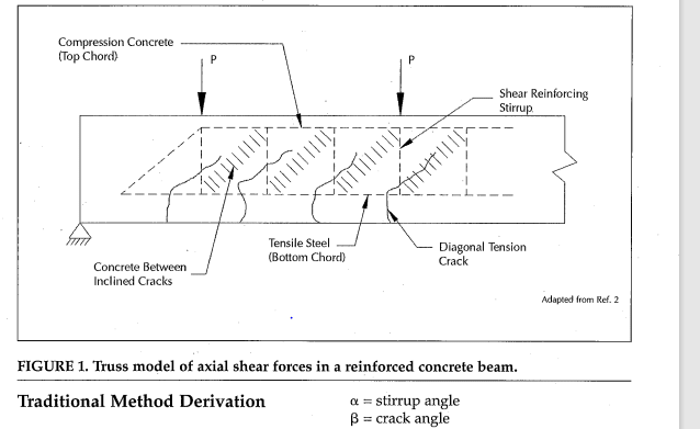
I suspect that you've confused strut and tie modelling with the truss model of shear resistance. Those are two very different things. I believe MFCT addresses deficiencies with the truss model of shear resistance, not the modern strut and tie modelling approach. Read all about it here: Link.

Saying that the ancient truss model of beam shear resistance is true, modern STM is a bit like saying a "car" is a Ferrari.

C01_ybnqeo.png
 
centondollar said:
It is more of an art than a science, for the reasons I have laid out in this post, and the literature will support this claim.

You've mentioned the literature supporting your positions repeatedly. Would you be so kind as to show us some of that literature so that we might digest and evaluate it for ourselves?

I have a special interest in strut and tie modelling and posses much of the seminal literature on the topic. In all of my travels you are the very first person that I've ever known to refute that STM is a lower bound method.

Are you able to point us to anything in print that would suggest that you are not entirely alone on planet earth with respect to your belief that STM is an upper bound method?
 
centondollar said:
Converging a STM model is, however, not as straightforward as converging a finite element solution.

In all of the STM design examples that I've reviewed from ACI, FIB, Schlaich, numerous US DOT's, and others I have not once seen anyone attempt to "converge" an STM model. It seems to be you and you alone who feel that is necessary. I believe that an STM model requires no "converging" because:

1) STM models are in equilibrium with their external loads by definition.

2) Any approximations made in the development of STM models are well within the range of normal engineering approximation.

3) STM is a lower bound method.

Can you point to any example that we might review in which someone has attempted to "converge" and STM model? We pretty much always attempt to have our STM models mirror elastic stress distributions but that's done at the beginning of the design process and is not at all iterative.

I submit that no one is "converging" STM models because they don't require converging.

 
centondollar said:
Regarding selection of STM, it is not comically simple. The reason? Precisely what you point out: ductility is not an easily measurable quality (for RC, steel or any other material).

Ductility is, in fact, very easy to measure. The trick is that you measure it in a laboratory setting. Then you use the results of that laboratory testing to inform the simplified design procedures used by engineers in practice so that they are not stuck with the onerous task of somehow trying to calculate how ductile a thing is on the fly. This process is basically what allows us to have "connections" in all of our favorite materials.

I presume that you are aware of the significant amount of testing that has be done to validate the strut and tie method of concrete design over the years? Many of the code provisions that govern strut and tie design exist, in part, to ensure that the members possess enough ductility for the STM method to be valid. This includes things like:

1) Limits on max/min strut angles.

2) Requirements for side face reinforcing in beams.

3) Requirements for transverse reinforcement to confine struts.

....
 
I've been putting off diving into strut & tie in any significant way because it has little utility in my work and time is scarce. But....I can't well sit idly by while people argue if it's lower bound vs upper bound, leaving me more discombobulated than when I opened the thread!

Just ordered:

Strut & Tie Model for Beginners
Structural Concrete: Srut-and-Tie Models for Unified Design


Any recommendations to add to the list?
 
With all this talk of STM and what have you - I found this lecture on Compatible Stress Field Method and the development of software for same to be completely fascinating. Perhaps you guys will enjoy. He also discusses many of the items in the (concrete related) discussion in this thread. And bond strength models :-0

I'm a bit / a lot of a layman when it comes to STM stuff so I have no opinion on this other than "neat!". (I'm not affiliated with idea statica)
 
Enable said:
Any recommendations to add to the list?

1) Paid. The Chen book that you purchased is actually my favorite text for a deep dive on the state of the art. Well done.

2) Free. In my opinion, the best beginner's guide on strut and tie is still the 1987 one by Schlaich that kinda got the ball rolling on modern STM: Link. Even if you didn't care about STM, this is worth a read merely as a view to the inner workings of the mind of a genius.

3) Free. The US Fedral Highway Administrations have a ton of high quality, free resources available. This is just one example of many: Link.

4) Free. PCI has a beautifully formatted little ditty on beams: Link

5) Paid. ACI has a nice, 2021 guide document out: Link

6) Paid. ACI SP-208 & SP-273 STM examples: Link

7) Paid. MPA's Concrete Center Guide to STM models (Euro): Link


Status
Not open for further replies.

Part and Inventory Search

Sponsor