Continue to Site

Eng-Tips is the largest engineering community on the Internet

Intelligent Work Forums for Engineering Professionals

  • Congratulations MintJulep on being selected by the Eng-Tips community for having the most helpful posts in the forums last week. Way to Go!

Flexural Strength Using Elastic Distribution 6

Status
Not open for further replies.

CDLD

Structural
May 20, 2020
218
Hello everyone,

The current AISC A360-16 Spec calculates flexural strength based on plastic section properties for the most part.
If you wanted to calculate the flexural strength based on the principles of elastic distribution how would you manipulate the equations provided in chapter F2 (doubly symmetric i-shapes)to do this (A360-16)

Do you agree with the following?

1. Yielding. Mn = Mp = Fy*Sx

2.Lateral torsional buckling.

Lp<Lb<Lr (inelastic buckling)
Mn = cb[Fy*Sx - (0.3 FySx)*((Lb-Lp)/(Lr-Lp))]< Fy*Sx (similar to provisions in chapter F5)

Lb>Lr (elastic buckling)
no changes.

The reason why I am curious is because, the code recommends using elastic distribution when combining flexure and torsion.
 
Replies continue below

Recommended for you

Are you trying to predict actual behavior in the elastic region, or are you trying to check strength against code requirements?

Where are you seeing the recommendation to use elastic distribution? (It sounds familiar, but I can't put my finger on the text.)


Well, both.
In the commentary H3-3 (p.368)
Also, I remember it being mentioned in AISC design Guide 9 and in an AISC Webinar about the design guide.
 
1. Yes, you can express Mnx = FySx.
2. Since you are performing elastic analysis, isn't inelastic buckling way out of its range?
 
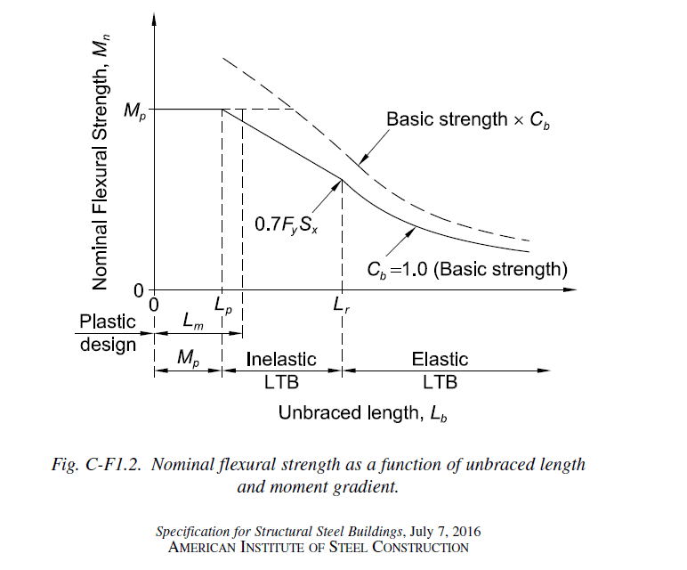
That's what i thought at first too, however elastic buckling actually starts at 0.7*Fy*Sx, which means that there can be inelastic buckling
You can this in the graphs in the commentary
 
CDLD said:
1. Yielding. Mn = Mp = Fy*Sx

That would be the case if flexure were your only demand upon the section. With torsion in play, you will need an interaction equation to verify that the combined stresses remain elastic.

CDLD said:
2.Lateral torsional buckling.

This part intrigues me. I believe that you can actually use the inelastic buckling equation with no modification whatsoever (still use Mp even). See if you buy this logic:

a) The inelastic buckling equation is saying "this beam possesses the torsional stiffness required to resist LTB up to a moment demand of [X] assuming some degree of inelastic flange strain".

b) If you design your beam such that no inelastic flange strain would occur, does that mean that it's torsional stiffness is somehow no longer adequate to meet a moment demand of [x] without LTB? I don't believe that it does.

If anything, I suspect that limiting flange stresses to the elastic level would increase LTB capacity relative to the inelastic buckling capacity. A flange that stays elastic has a higher lateral moment of inertia and thus produces a torsionally stiffer cross section.

CDLD said:
The reason why I am curious is because, the code recommends using elastic distribution when combining flexure and torsion.

My understanding of that recommendation is that:

1) it is meant to apply only to the determination of maximum stresses (real stresses, not fcr stuff) in the beam that would result from the combined actions of flexure, torsion, and shear and;

2) it is intended to relieve us of the impractical burden of trying to work out beam capacity when our beam flanges are simultaneously being taxed to yield in flexure and bent laterally as a result of torsional warping stresses.

Other than maxing out capacity at [phi x (Sx x Fy - warping torsion normal stress)], I feel that the design would remain unchanged relative to a conventional, plastic design.

 
CDLD,

I don't know where you get the elastic buckling strength (0.7fySx) from, but for elastic analysis, when compression buckling occurs prior to tension yield (as in this case), the distortion is large, and the member is considered failed. I think inelastic behavior can only occur when tension yield has occurred prior to compression buckling. I could be wrong though.
 
I agree that using elastic distribution for flexure is conservative, especially in the cases where you have minimal torsional stress.
I am also aware that there are interactions out there that allow you to use plastic distribution for flexure in combination with torsion. See section 3.1 in attachment

Despite that, I would like to respect the AISC's conservative approach and use the elastic bending resistance.
This would be the interaction: f(bending)/F(elastic bending resistance) + f(warping)/Fy

KootK, if you had to calculate the elastic bending resistance in the inelastic buckling range, how would you do it?
 
 https://files.engineering.com/getfile.aspx?folder=c04fb821-5b36-4d14-b426-911e7b99b436&file=Torsion.pdf
CDLD said:
Despite that, I would like to respect the AISC's conservative approach and use the elastic bending resistance.

That's where we differ. I am confident that you would respect AISC's approach in it's entirety without considering failure modes related to stability in the "keep it elastic" combined stress check.

CDLD said:
KootK, if you had to calculate the elastic bending resistance in the inelastic buckling range, how would you do it?

Using this equation without any alteration whatsoever and then using the lesser of that value and the "keep it elastic" combined stress check with no consideration of LTB in the latter.

c01_hibyu3.jpg
 
I'm going to quibble over a few minor details for a little bit. Forgive me for being a little annoying.
1) If you're using yielding as a limit state then, Mn = My = Fy*Sx
Keep in mind that Mp refers to "plastic Moment" of the cross section, where the entire cross section has yielded.
Also, My refers to the yield moment of the section where the extreme fiber has reached yield.
2) That equations seems reasonable.

3) Regarding section H3.3: That section of the AISC specification is absolute garbage. It just doesn't work with the rest of the code. Granted, if you have some really good engineering judgment you can probably get past the flaws and use this section.

That being said, let me elaborate on the flaws and propose a better way of dealing with torsion in non HSS members.
a) If you have a member whose torsional stresses dominate and only has a little bit of bending H3.3 may work fine.
b) If you have a member where both torsion and flexure are significant that section will likely be too conservative. Not only that, but the section just isn't based on very sound fundamental principles. Better to use Design Guide 9 as your starting point.
c) If you have a member where bending is significant, but where torsion is probably pretty minor (i.e. most cases for wide flange and channel members) then H3.3 is absurdly conservative. Let's say you ignore the torsional moment (which is truly insignificant) then pick a member (based on Mp) which as an Mu/(Phi*Mp) = 1.0. If you then you H3.3 that member is significantly overstressed. This is because H3.3 is not compatible with the rest of the code and results in discontinuities in capacity when you introduce it using even the smallest torsional moment.

This isn't a big deal to humans. But, it is a big deal to computer programs.... Which is why I hate this section of the code so much. Because I have spent the majority of my career working on structural engineering computer programs. There just isn't a good way to incorporate this section into a computer program.

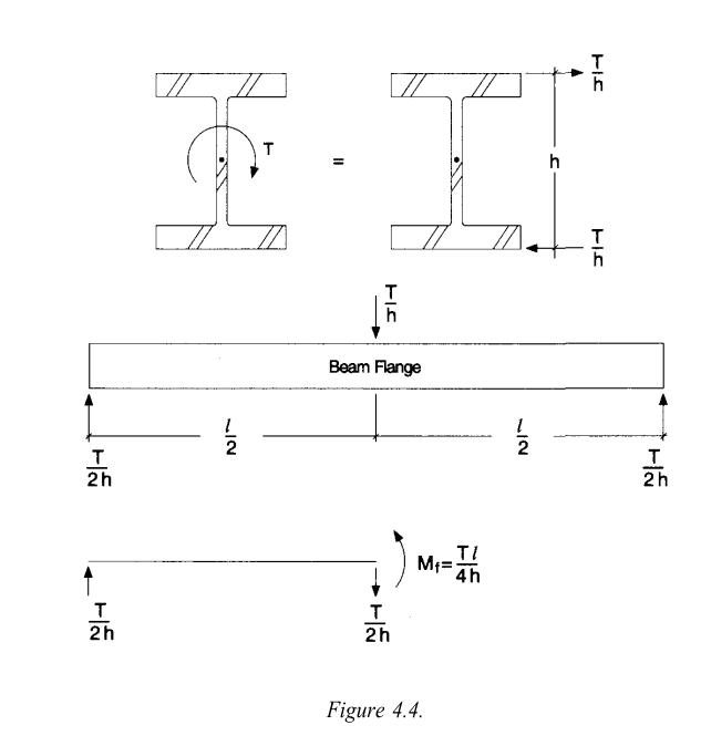
4) Now, AISC design guide 9 does have some better suggestions. For code checking a wide flange member vs torsion (by hand) there is the "equivalent tee" method. Where you convert the torsion into a weak axis bending moment in an equivalent tee cut from the wide flange.
image_l9jij9.png

That is good for doing hand calcs and getting an idea of what sort of warping stresses will develop in a member. You can then convert these stresses into an equivalent weak axis moment that would produce that stress on the original wide flange member. Then increase whatever your original weak axis moment was by this amount and use regular H1.1 code equations to check the member. This (IMHO) is way more rational than whatever H3.3 is doing. Granted, you also have to include torsional shear stresses in your shear code checks.
 
My suggestion is not to mix elastic analysis with plastic analysis. Two different design universe and rules.
 
JoshPlumSE,

Oops, the Mp slipped into there somehow in my original post.
I agree with everything you said.
H3:3 doesn't transition well with other parts of the code. And can be problematic when reinforcing existing members that were designed to full plastic limits.
However, I have no problems swallowing this conservative approach for design of say new crane girders with torsion or monorails.

So you agree with the LTB equation in the inelastic range that i posted, which will linearly interpolate between My and 0.7FySx(start of elastic buckling)
 
Yes, those equations seem reasonable for the inelastic range. They're based on the assumption that the web is slender (which it's not) and that will prevent the member from reaching stresses above Fy. So, that would seem to agree nicely with the restrictions of H3.3.

Personally, for crane rails I very much prefer the concept of a wide flange with a cap channel. Where we use the strong axis bending of the channel to take what would have been torsion for the wide flange. Then ignore the channel and use the strong axis of the wide flange for the vertical bending loads on the girder.

Granted, it's possible that this could end up being more conservative than using H3.3.
 
KootK

What you are saying is interesting.
I've never interpreted the "keep it elastic" that way.
So, you're essentially saying design for flexure according to the spec (plastic and all) and then make sure your resistance doesn't surpass My (first yield)

I always figured they meant to interpolate from My to the 0.7My for the inelastic range

What do you think of section F5 of the code? (For plate girders and mono-symmetric beams)(You can conservatively use this rather than section F4)
They keep this section totally elastic, and you'll notice in F5-3 they interpolate between My and 0.7My for the inelastic range.
 
OP said:
Mn = cb[Fy*Sx - (0.3 FySx)*((Lb-Lp)/(Lr-Lp))]< Fy*Sx (similar to provisions in chapter F5)

JP said:
They're based on the assumption that the web is slender

Can you elaborate? I don't believe that the equation above makes any assumptions at all about web slenderness.
 
@JP: disregard my last comment. I'm now fairly certain that you were referring to AISC equation F5-3.
 
KootK chapter F5 can be used for plate girders that have slender webs.
You can conservatively use this section to elastically design plate girders that do not have slender webs (this is stated in F4)by setting Rpg = 1.

I guess I answered my own original question there eh.
 
CDLD said:
I always figured they meant to interpolate from My to the 0.7My for the inelastic range

Who are "they"? 0.7My=0.7FySx, 0.7Fy is in the inelastic range? I am confused.
 
OP said:
So, you're essentially saying design for flexure according to the spec (plastic and all) and then make sure your resistance doesn't surpass My (first yield)
.

Yes, except for the part that is bolded which needs to account for this:

KootK said:
That would be the case if flexure were your only demand upon the section. With torsion in play, you will need an interaction equation to verify that the combined stresses remain elastic.

CDLD said:
What do you think of section F5 of the code?

1) I can see how you might have assumed that section to set a precedence for what you're trying to do with torsion.

2) As with the regular LTB equation, I feel that F5 does not limit the combined (flexure + torsion) stress to Fy as AISC intends.

3) As Josh mentioned (I think), F5 is limiting flexural stress, and only flexural stress to Fy as a means of preventing a slender web from buckling. It's not designed to address torsion interaction in any way and, where a beam web is not slender, the equation will limit capacity unecessarily.
 
retired13,

I was referring to the author's of the A360-16 spec.

Here, look at this snip. You're probably familiar with it.
Annotation_2020-06-18_152340_p1491z.png
 
Status
Not open for further replies.

Part and Inventory Search

Sponsor