Continue to Site

Eng-Tips is the largest engineering community on the Internet

Intelligent Work Forums for Engineering Professionals

  • Congratulations MintJulep on being selected by the Eng-Tips community for having the most helpful posts in the forums last week. Way to Go!

Flexural Strength Using Elastic Distribution 6

Status
Not open for further replies.

CDLD

Structural
May 20, 2020
218
Hello everyone,

The current AISC A360-16 Spec calculates flexural strength based on plastic section properties for the most part.
If you wanted to calculate the flexural strength based on the principles of elastic distribution how would you manipulate the equations provided in chapter F2 (doubly symmetric i-shapes)to do this (A360-16)

Do you agree with the following?

1. Yielding. Mn = Mp = Fy*Sx

2.Lateral torsional buckling.

Lp<Lb<Lr (inelastic buckling)
Mn = cb[Fy*Sx - (0.3 FySx)*((Lb-Lp)/(Lr-Lp))]< Fy*Sx (similar to provisions in chapter F5)

Lb>Lr (elastic buckling)
no changes.

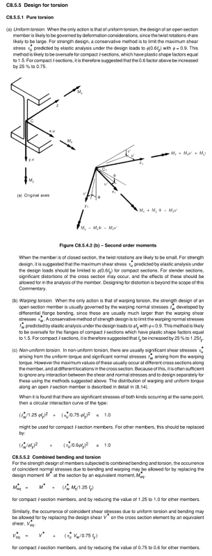
The reason why I am curious is because, the code recommends using elastic distribution when combining flexure and torsion.
 
Replies continue below

Recommended for you

KootK,

How do you ensure the "combined stresses remain elastic"

This is my interpretation of "combined stresses remain elastic":

1. Determine the bending stress (M/Sx) and divide it by the elastic bending resistance based on the equations from my first post(LTB and all)
2. Determine the warping stress and divide it by the yield stress.
3. Add them together and hope they are less than 1 (assuming they happen at the same location)


KootK, I think the whole point of checking everything in elastic is because AISC hasn't come out with an interaction for using the plastic equations.
I'm pretty confident what i outlined above is a conservative approach.

Agree?
 
I see, it is elastic/inelastic range of buckling, not yield. So the inelastic range is 0.7FySx to FyZx (Mp). Thanks, as I am not aware of that.
 
CDLD said:
This is my interpretation of "combined stresses remain elastic":

1. Determine the bending stress (M/Sx) and divide it by the elastic bending resistance based on the equations from my first post(LTB and all)
2. Determine the warping stress and divide it by the yield stress.
3. Add them together and hope they are less than 1

Yes, I think that is the way to do it. Though H3.3 doesn't ever really look at combined stresses, but that is how I would probably do it.

However, I would point out that you'd also want to look at shear stresses to make sure they are less than 0.6Fy. That's the combination of maximum flexural shear stress and maximum torsional shear stress.
 
Josh,

Agreed.
They don't actually specify in the commentary or the spec but it's in Design guide 9.
It actually does provide an interaction for combining torsion, bending, and axial forces.
It's as you'd expect.
 
CDLD said:
How do you ensure the "combined stresses remain elastic"

M/Sx + Warping Torsion Normal Stress < Fy/phi. I like JP's recommendation on the bi-moment method for the warping. That's what I usually do myself.

CDLD said:
KootK, I think the whole point of checking everything in elastic is because AISC hasn't come out with an interaction for using the plastic equations.

And they probably never will come out with an interaction equation because it's a wildly complex and difficult to predict situation. The root issue is this:

1) The lateral stiffness of the flanges about their own strong axes is the primary source of the beam torsional stiffness that resists LTB.

2) If the flanges go plastic from bending, what is the lateral stiffness for #1? It's that to be had from a plastified flange being unloaded flexurally on one side as lateral buckling initiates.

3) If #2 were not complex enough, the addition of torsion is changing the stress distribution in the flanges and altering the point in the load history when they plastify and unload.

4) If #2 & #3 were not complex enough, torsion and bending graphs do not parallel one another along the length of a beam. Torsion tends to look more like shear.

5) If #2, #3 & #4 were not complex enough, LTB is a phenomenon occurring over a discrete length whereas torsion stress is a cross sectional phenomenon.

That's a lot to take on with an interaction equation. Keeping things elastic makes a lot of that go away.

CDLD said:
I'm pretty confident what i outlined above is a conservative approach.

Yes, excessively so and in a manner that is not entirely consistent with theory. You asked how this should be done and I gave you my best in that regard. Max capacity & consistent with theory. If you prefer something more conservative, so be it.
 
Suggest to stick to ASD, or LRFD for design, then apply safety factor in accordance to the level of conservatism of your desire, so there is no confusion.
 
KootK,
I mostly agree but you have to know that the bi-moment method is wildly conservative for long spans, even more than the method I proposed.
Also, I think adding the warping and the bending stresses and checking them against yield isn't conservative.

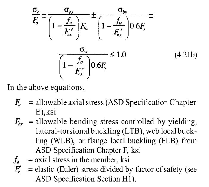
Look at this interaction from DG9.
Bending stresses should be checked against bending resistances
Annotation_2020-06-18_171522_te0r8z.png
 
KootK said:
Yes, excessively so and in a manner that is not entirely consistent with theory.

That needs to be dialed back a bit. Let's try this:

Yes, in a manner that leaves some capacity on the table unnecessarily and that is not entirely consistent with theory. My use of the term excessive was.... excessive. I don't expect the difference to be all that large.
 
CDLD said:
I mostly agree but you have to know that the bi-moment method is wildly conservative for long spans, even more than the method I proposed.

That's a moot point as far as my proposed method goes. I don't much care how you calculate warping stress so long as you do calculate them in a defensible manner and consider their interaction with other stresses. I don't use bi-moment because I think that it's the most accurate method; I use bi-moment because it's generally conservative and I feel that it's the most profitable method for me.

CDLD said:
Also, I think adding the warping and the bending stresses and checking them against yield isn't conservative.

Why not? I feel this part of it is just basic mechanics of materials.

Remember that hand calculated, bifurcation buckling simply estimates the approach of a neutral stability condition. At "buckling", nothing has actually happened physically. Nothing has moved and no additional stresses have been generated as a result of the buckling. In a fundamental way, this is why buckling does not add to the stress burden of the material. Bifurcation buckling adds stress after failure and not before it. Generalized instability with consideration of imperfections is different but that's not what we're doing with the AISC hand calculation methods.

CDLD said:
Look at this interaction from DG9. Bending stresses should be checked against bending resistances

1) This would be the equations most germane to this discussion I think.

2) This equation represents a capacity check rather than a cross sectional stress check to determine whether or not everything remains elastic under the action of combined stresses. Those two things are quite diffent. Apples and oranges.

3) The second term of the equation supports my position on this in that Fbx encompasses the beam LTB check calculated in the normal manner, with Mp rather than My.

c01_hde6nk.jpg
 
KootK,

Looking at this with some fresh eyes, I'm starting to pick up what you are putting down

This is the gist of it:

1. Elastic Stress Check
- Add axial stresses, warping stresses, weak axis and strong axis stresses and divide by yield stress , <1

2. Check the capacity using the equation you posted above
- Using full plastic resistances from the spec

Any reason why they have to different notations for axial stress in equation 4.21b?

Thanks for your help on this.
 
Hi CDLD,

The strength due to the limit state of lateral-torsional buckling under combined torsion and flexure can determined as follows.

1) Calculate the required normal stress due to combined flexure and torsion (fun).

2) Calculate the nominal flexural strength due to the limit state of lateral-torsional buckling using AISC 360 Chapter F, without making any modification (Mn).

3) Calculate the buckling critical stress as follows.
Fn = Fcr = Mn/Sx (H3-9)

4) Check: fun < φT*Fn

A similar approach may be used for the limit state of local buckling.

Take a look at the design example H.6 of Companion to The AISC Manual.


Hope this help!
 
KootK -

That equation from design guide 9 (which uses axial stress to amplify torsional warping stresses) brings something to mind that I don't often think about.

When I was regularly attending the AISC committee meetings, a couple of the professors there were concerned about one aspect of the P-Delta effect that they didn't believe was considered adequately in most commercial analysis programs. And, that was the effect of axial force on torsional defection of a member. This is something that can be done with the geometric stiffness modification method of P-Delta analysis. However, most programs (I believe) don't do this. In the same way that most programs don't include the stiffness effects of torsional warping on WF and channel members.
 
CDLD said:
Any reason why they have to different notations for axial stress in equation 4.21b?

That is odd as I agree, despite the different notations, the values should be the same. My guess is that the author was struggling to maintain consistency on two fronts:

1) The stuff in the denominators is old hat, AISC steel design. I imagine the author wanted to keep that stuff looking the same as it does in the spec, manual, etc.

2) The stuff in the numerators looks all nice and logical when it's all expressed with the greek sigma thing. It's a bit awkward because, with modern steel flexure provisions, we don't really operate in terms of stresses any longer.

CDLD said:
Thanks for your help on this.

You're most welcome. And thank you. It's been fun and I've learned much myself.
 
PROYECTOR / AISC EXAMPLES said:
3) Calculate the buckling critical stress as follows.
Fn = Fcr = Mn/Sx (H3-9)

I disagree with that step on two fronts:

1) It's logically inconsistent to calculate an LTB capacity using plastic principles and then prorate it with an elastic section modulus. Again with the apples and oranges.

2) It overestimates capacity. Since Zx > Sx, dividing by Sx will actually inflate the critical buckling stress in a way that is inappropriate.
 
JP said:
When I was regularly attending the AISC committee meetings, a couple of the professors there were concerned about one aspect of the P-Delta effect that they didn't believe was considered adequately in most commercial analysis programs. And, that was the effect of axial force on torsional defection of a member.

Fascinating. I've never thought of this even once. I suppose that as the flanges flex under warping, any imposed axial loads at the end amplifies that flexing just as it would for a traditional column.

JP said:
This is something that can be done with the geometric stiffness modification method of P-Delta analysis.

Do you know if it can it still be done with a stick element representing the beam? Or do things have to get fancier than that.

For now, I think that I'll just steer clear of designing any torsion beams with heavy axial. My poor brain can only handle so much...
 
Kootk said:
I disagree with that step on two fronts:

1) It's logically inconsistent to calculate an LTB capacity using plastic principles and then prorate it with an elastic section modulus. Again with the apples and oranges.

2) It overestimates capacity. Since Zx > Sx, dividing by Sx will actually inflate the critical buckling stress in a way that is inappropriate.

Yes, there is an obvious inconsistency in this equation. However, I think it is still a conservative and simple enough approach considering that the beam will have more strength beyond the elastic range. There is an intrinsic conservativism in using an elastic stress distribution for design and I think using Zx instead of Sx in this equation takes this conservatism to far. I think this could be the intent of who prepared the example H.6 of Companion to The AISC Manual.

I also think the JoshPlumSE's approach is more rational and simple, I usually use that approach for designing wide flange sections with lateral loads near the top flange (e.g., crane runway beams). However, if the intend is to satisfy the H3.3 requirements, the procedure described in example H.6 is more appropriate, even if it is not entirely theoretically correct. A good design model is one that produces sufficiently accurate results in a reasonable amount of design time.
 
KootK said:
Do you know if it can it still be done with a stick element representing the beam? Or do things have to get fancier than that.

It can be done with a regular beam / column element (12 DOF member). In the similar way we account for P-little delta effects with a geometric modification to the stiffness matrix.

The best textbook that I've seen on this subject (frame analysis) is the following, which is now a free download from Bucknell's website:

Matrix Structural Analysis by McGuire, Gallagher, and Ziemian

The reference doesn't get into more advanced topics... like plates or solids or such. But, it is excellent for frames.
 
I've got that one (hard copy even) and used it extensively in grad school. Does it actually cover the torsion business?
 
It covers torsion within the context of geometric adjustment to the stiffness matrix.

It doesn't cover torsional warping's effect on the stiffness of WF and channels. However, it points to some reference papers on the subject. I haven't read them. But, they sound like what is needed for one of these programs to really do warping correctly.

Note: Ron Ziemian (one of the author's of the book) is the author of the MASTAN program. While that program is mainly for academic purposes, I'm pretty sure it does a good job with torsional warping stiffness. Some I'm confident that those papers do describe what we'd need to really, truly do this correctly.
 
Just to throw another non AISC code perspective into the mix. The following is from NZS3404, it takes quite a different approach to the interaction of torsion/warping and moment than the purely linear interaction equations which have been predominantly discussed above. This is possibly in recognition of some plasticity actually being acceptable (i.e. flange tips) and the fact that maximum stresses are not always coincidental across a cross-section which is important to recognise if you are truly after the 'elastic' stresses throughout the entire cross-section. Most ultimate limit state 'plastic' based derivations of combined actions do not do this, they accept some level of plasticity on the basis that stability of the cross section is still maintained. So they are not really suited to fudging to ensure every point in the cross section has a stress less than the yield stress. These formulations accept some plasticity and redistribution of stresses to result in more efficient design capacities being achieved under ultimate loads.
Annotation_2020-06-21_123934_kxvzu5.png

Secondly, if you are trying to keep it all elastic, what would be wrong with looking at the principle stresses from a fundamental first principles analysis approach. You know all of the design actions (presumably), axial, torsion, shear & moment about both cross-section axes, so just look at the 3D stress state. Obviously, you need to find where it is critical, but that's just running sufficient locations until you understand what contributes to the critical stress state and compare that the strength reduction factor times f_y. Something like this is free and would enable you to automate the process under any combination of loads to give you some insight to where you sit on the spectrum of elastic stresses (or plasticity).
 
Status
Not open for further replies.

Part and Inventory Search

Sponsor