Eng-Tips is the largest engineering community on the Internet

Intelligent Work Forums for Engineering Professionals

  • Congratulations waross on being selected by the Eng-Tips community for having the most helpful posts in the forums last week. Way to Go!

Floor Joist and Beam Uplifts at Three-Point Bearing

Status
Not open for further replies.

GlulamSam

Structural
Mar 21, 2022
10
US
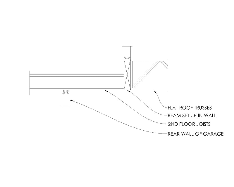
I am working on a residential project with an interesting framing layout. What I have is a second floor that does not align with the main floor wall below. I have a large glulam beam that will be "set up" so that it does not drop down below the bottom of the floor joists. I have floor joists for the second floor that hang into the beam on one side. The other side of the beam has a flat patio roof that hangs into it. See the framing layout below.

I am having some issues with two items. The first issue is that the floor joists span approximately 21' feet to the garage bearing wall and then they go an additional 4' to get to the glulam beam. My calculation shows that if the floor joists hang into the glulam beam they will each put a rather large uplift load into the beam. Should I not detail the joists to hang into the beam, but cantilever instead? Should I note that the joists should break at the bearing wall so they aren't continuous joists? My worry with both of these ideas is that I am 100% that any detail or note I put on the plans will not be done correctly. The framers will hang the joists to the beam. If they do that, will that be a major problem later on? Will the floor joists explode out of the hanger and pull the sheathing up? Will nothing happen?

The other item I'm worried about is very similar. If I calculate the large glulam beam to bear in 3 locations then I have a massive uplift at Support 3. I considered designing the beam to cantilever past Support 2 and put a note on the plans telling the framer to NOT bear the beam at Support 3. Again, I am confident that the framers will bear the beam at Support 3. I have an uplift force of 7,000 lbs. in that location if I design the beam to bear there. What will happen if they do indeed bear the beam at Support 3? Will the connection "fail" and then it ends up going back to my cantilever design? Will it pull the floor sheathing and wall up with it?

My calculations show these large uplifts for the floor joists and the beam. What will actually happen in real life if the framers build it how I suspect they will? Would appreciate anyone's experience/knowledge on this topic. Thanks!
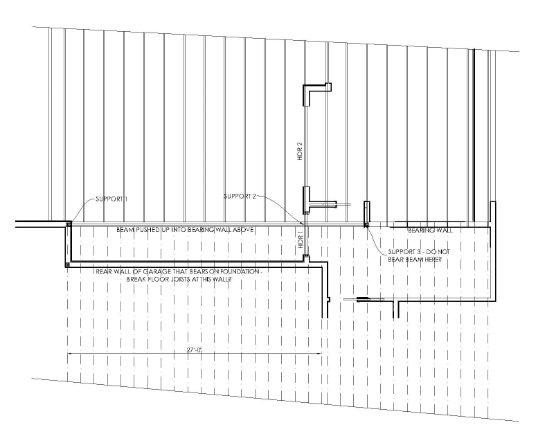
Uplift_Joists_Plan_View_o1etmc.jpg
Uplift_Joists_Cross_Section_ustt9r.jpg
 
Replies continue below

Recommended for you

You could look into what is the upward tip deflection of these propped cantilevers. Consider how that movement might affect the adjacent structure.

I think your idea of breaking the spans into multiple simple spans is the most direct way to address your problem.

Detail it and show it well how you want it. If they build it differently and you see it then show them the detail and make them do it right. If you never hear about it, well then that's a construction issue. If your concerned that it wont get built the way you want bring extra attention to those details to the inspectors or require a special inspection on those details alone.

You can't control everything in the field but you can control your drawings.
 
Get rid support 2 and design the beam to span to support 3. Use deeper beam (not wider than 5.5").

The other option is make support 3 farther on the right to make it more equal distance.

As far as the joists go, I would just bear it on the wall plus the 4 ft to the beam. I would specify face mount hangers because those have good uplift value. Don't use top flange hanger. Make sure your force works out on the ledger and the face mount hanger to resist uplift. Dont forget to put blocking at bearing on top of rear wall garage between joists.
 
The other option is to stop and start the beam at header. Specify 2 different beams.
 
I just want to throw an idea out in case it's something you'd want to consider.

We can design wood webbed floor trusses with 2 verticals over a bearing. We can hold the verticals apart an inch or so. After the floor trusses are set, the top chord can be cut between the verticals. Then the 2 spans act independently.

Yes, I'm well aware that the subfloor connects the spans together to some degree. I've never know that to cause any problems.
 
Thanks for the comments.

After running through some calculations I have decided that the uplift from the floor joists is not a big deal. I will call out some hangers with some good uplift capacity as mentioned by DoubleStud. The beam is carrying a lot of other loads, so the uplift from the joists ends up being negated by all the other downward forces into the beam.

Now I am still considering options for the BEAM.

DoubleStud said:
The other option is make support 3 farther on the right to make it more equal distance.
Yeah this is the solution I want to go with, but I also want to consider the pain and anguish I'll have to go through later on if they don't do this correctly. In my experience I could note this on the plans in flashing red lights and they'll still bear it where I show Support 3 on the drawing above. I think this is the best solution, but I'm trying to make sure there isn't anything "simpler" for the framers to do so there's a smaller chance of messing it up.

DoubleStud said:
The other option is to stop and start the beam at header. Specify 2 different beams.
I don't think this works in my case. My calculation says that if I separate the beam into 2 different beams then the longer span beam will need nearly 4.25" of bearing length. If I split the beams over the 2x6 wall then there won't be enough bearing length to carry the reaction.

DoubleStud said:
Get rid support 2 and design the beam to span to support 3.
Support 2 is at the exterior wall of the home. I could design the beam without Support 2, but if the framers put a few toenails from the beam into Support 2 would that negate my whole design and put a big uplift into Support 3? I guess I don't really understand the effect that "tying" the beam down to Support 2 would have on Support 3.

As I mentioned in the original post I am considering designing the beam to bear at Support 2 and then cantilevering for the last few feet. I would note on the plans to stop the beam short of the wall where I showed support 3. I don't see any issues with this solution, excepting again for the potential of it being framed incorrectly. Although, since the floor sheathing kind of ties everything together then is there any point in stopping the beam short of Support 3 when the diaphragm is essentially tying the beam to Support 3 anyway?
 
Use two simple spans, Support 1 to 2 and 2 to 3. And give the architect a boot in the arse.
 
BAretired, you maybe didn't see this in my last response but using 2 simple spans doesn't work since there won't be enough bearing length available. The span from Support 1 to Support 2 needs a bearing length of 4.17" since the reaction at that location is about 14,000 lb.
 
As far as the beam goes, I think you have two options:

1. Run a design with the beam cantilevering past support 2, then increase the beam depth until you have sufficient stiffness and the upwards tip deflection is reduced to a point you're comfortable with.

2. Cut the beam at support two and get creative with the bearing. For example if you need a 5.25x20 beam, bear it fully on support two, then notch the top 8" of the beam back 3". I would check the shear capacity of the remaining section, although you could argue this won't impact the shear capacity of the beam at all. Then cut the reverse notch on the short beam, extending the top 8" of the beam 3" to sit on this pocket. We do this fairly regularly using two different beams sizes when we want the tops of the beam to align...it's a little counterintuitive if you're using the same beam size all along (the framers will ask if they can just run it the whole way), but you will want the deeper section on both sides to align the bottom of the beams in your case.
 
GlulamSam,

Simple spans are best. Give the longer beam full bearing. Hang the short beam off the end of the long beam. If you are still tight for bearing area, widen Beam HDR 1 or use a base plate. Any way you slice it, the reaction at Support 2 will be less using two simple spans rather than one continuous span.

Capture_gqr6ej.jpg
 
@GlulamSam,

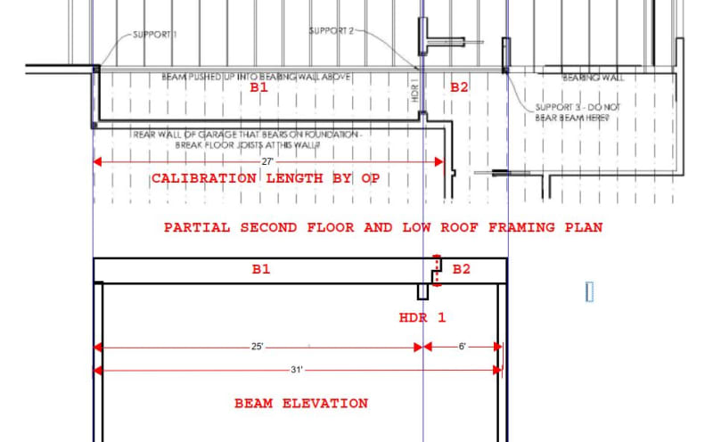
Based on the 27' dimension provided, the spans of B1 and B2 are 25' and 6' respectively.

If the load is 'w' on both beams, B1 has a fixed right end moment of w(25)[sup]2[/sup]/8=78w.
If B1 is continuous over three supports, the cantilever moment would be w(6)[sup]2[/sup]/2 = 18w,only one quarter of the fixed end moment. That means the reaction at support #3 must be -60w/6 = -10w; a negative reaction at support #3 means a substantially larger reaction at support #2.

That is why two simple beams should be used.

Capture_ejxypz.jpg
 
BA's detail for hanging the B2 beam works, but I'm more partial to having the B2 beam sit on top of the B1 beam, essentially just flip the notches. I've done this quite often.
 
Thank you for your insights everyone.

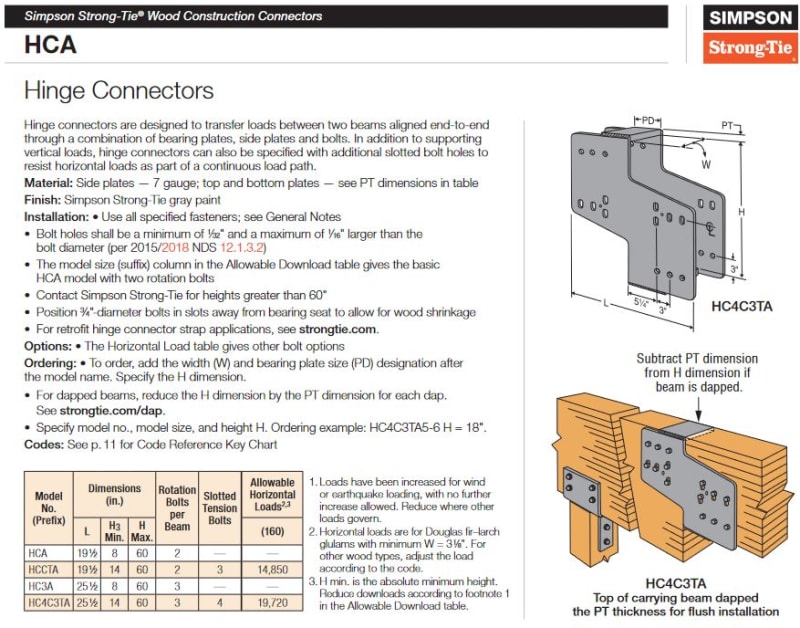
How would you feel about a connector such as this HCA from Simpson? Their diagram is a little different from mine since my beams would be the same height, but it's the same idea. With this connector the beams wouldn't need to be notched. I want to make sure that the connection doesn't end up tying the beams together in such a way that it acts like a single beam. BA's sketch shows a through bolt at the notch location. I'm not sure whether the through bolt or this HCA connector will allow the beams to move more independently.

Simpson_HCA_kcznom.jpg
 
jayrod's suggestion seems okay to me, in fact, in this case, it may be an improvement. Ordinarily, I don't like to do that because the reaction tends to split the beam horizontally at the re-entrant corner but in this case, B2 will have more shear strength than required, so not a problem.
 
Makes sense BA. Often in my situations it's where a far shallower beam is framing into a deeper one, so the shallow beam gets little to no notch, and the deeper beam has a more than tolerable notch on the top.

The proposed simpson connector would also work. I'm not sure why you're saying you'd need one where the beams are the same depth. If you're cutting the beam into two spans, why not shallow up the short span accordingly for the loads? Save the homeowner some money.
 
jayrod12 said:
I'm not sure why you're saying you'd need one where the beams are the same depth.

Well I was thinking if I used the Simpson connector then the beams would need to be the same depth since the bottoms of the beams will need to be at the same height. I think the connectors are only for situations where the tops of the beams are at the same height. B1 bears on top of the wall top plates so I'd like B2 to also bear on the top plates at the right end of B2 where it sits on Support 3. If I go with through bolts as BA showed then I could have a shallower beam for B2.
 
Or just put a small post from underside of B2 down to the existing wall plate. That's nothing new or drastic.
 
Maybe this is an unrealistic fear, but I worry about a seismic event where the 8"-10" tall post is wobbly. I know the floor joists and sheathing hold the beam in place but that post could be a potential weak spot. Maybe I'm overthinking it.
 
Fair point I guess. I work in a non-seismic area.

In this case, my opinion is still that the risk is small provided there's adequate connections at the top and bottom of the post to the wall and beam. I feel in your scenario it's less concerning than a beam connected to a tall column.
 
GlulamSam said:
Maybe this is an unrealistic fear, but I worry about a seismic event where the 8"-10" tall post is wobbly. I know the floor joists and sheathing hold the beam in place but that post could be a potential weak spot. Maybe I'm overthinking it.

I'm not in an active seismic zone, but to me it seems like an unrealistic fear. B2 could be half the depth of B1 and bear on a notch on B1 with nominal hardware joining them together. That would seem to be the simplest detail. B2 can be laterally braced by the flat roof trusses...nothing wobbly about that.

Alternatively, HDR 1 could be wide enough to bear B1 and B2 if they both have the same depth (and if the architect agrees to the required header width).

HCA connectors are labeled hinged connectors, but if the beams are the same depth, they must be separated far enough to permit B1 to rotate at Support 2 without forcing B2 to rotate. I don't favor HCA connectors in this case.

As for the floor joists with the short span, I suggest you consider the suggestion of RontheRedneck earlier in this thread.
 
Status
Not open for further replies.

Part and Inventory Search

Sponsor

Back
Top