Continue to Site

Eng-Tips is the largest engineering community on the Internet

Intelligent Work Forums for Engineering Professionals

  • Congratulations KootK on being selected by the Eng-Tips community for having the most helpful posts in the forums last week. Way to Go!

Flow rate flunctuation

Status
Not open for further replies.

BA Joe

Petroleum
Nov 26, 2019
12
Hello Friends,
I have a sort of general question

1. A centrifugal pump is being used for an experiment that involves introducing some restriction in the flow path and the pressure changes measured. However, it was noticed that when this restriction is produced, the flow rate of the pump reduces compensating for the pressure increase.(I believe this is typical of centrifugal pump). Client wants to know and be sure that simply changing to a "displacement pump" will solve this flow rate flunctuation

2. What are the physical signs (if any) of cavitation in a centrifugal pump and Displacement pump?

Thank you.
 
Replies continue below

Recommended for you

That's a general question alright.

1) Correct - Basically a centrifugal pump is a constant pressure device (within 20%). As you introduce restrictions the flow changes.
A positive displacement pump or PD pump is essentially a constant flow pump (within 5-10%) and the pressure changes as the resistance to flow increases. This pressure rise is limited by the power of the motor only, so you normally need some protection (pressure relief / bypass valve) to prevent pressure rising too high for the system.

If you want to maintain flow with varying frictional losses in the pipework you can still use a centrifugal pump by having a higher pressure unit, but controlling flow with a control valve before your valve before your pipework or by varying the speed of the pump (VFD or VSD drive).

2) physical signs are
a) a "tinkling" sound
b) a reduction in differential head/pressure
c) pitting and erosion of the inner surface of the impellor

Does that help?


Remember - More details = better answers
Also: If you get a response it's polite to respond to it.
 
Thank you for the response "LittleInch".

Kindly see further enquiries below.

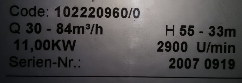
1. The attached link shows the picture of pump spec as seen on the pump body
2018-15-05_10.58.34_xh2ftq.jpg


However, the pump curves and other details are unavailable (not received from the manufacturer).
Now the picture shows a specified flow rate of 30-80M3/h, unfortunately the facility is currently operating this pump between 20-35m3/h. Is it safe to say the pump is underutilized and not working within its best optimum points. Can you deduce from this that the pump is probably experiencing cavitation because it is working below its specified range?

2. Can you explain further your suggestion in your previous response about maintaining constant flow with a centrifugal pump by use of valves.

3. Are there any external signs of cavitation?
 
You have two points on the pump curve. 30 m^3/hr at 55 mh and 84 m^3/hr at 33 mh.

Ted
 
I initially read that as 11MW, but it's the continental way of writing 11.00

Yes at an operating range below the range specified the pump is essentially too big and won't be operating efficiently, but will be using less power than at higher flows because it isn't doing the same amount of work.

It shouldn't be cavitating though unless other things are happening on the suction side as you're not giving us any real information here.

OK so for your pump duty here lets assume ( as you've not given us any data) that at your increased restriction you need lets say 50m of differential head from your pump to get the flow at lets say 50 m3/hr. Your current pump at 50 m3/hr only gives you say 40m.

So what you do is get a higher powered pump that gives you 50m at 50m3/hr. Or maybe a bit more so lets say 60m @ 50m3/hr.

To maintain 50m3/hr with a flow resistance of anywhere between 1m and 50m you install a control valve between the pump and the piping.

Then adjust the valve as the downstream resistance increase so that flow stays the same. The higher the downstream resistance the more the valve is open and vice versa.

Other than sound and a reduction in DIFFERENTIAL head, no signs. Why do you think it is cavitating?

Give us the whole story here and we can help you but drip feeding information is frustrating.

Remember - More details = better answers
Also: If you get a response it's polite to respond to it.
 
1. Client wants to know and be sure that simply changing to a "displacement pump" will solve this flow rate flunctuation

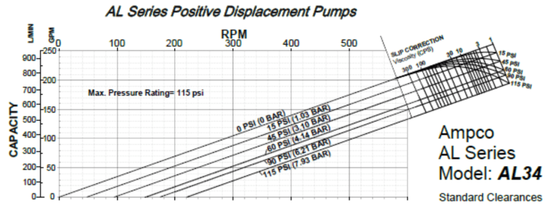
The answer is "it depends". If you are pumping water or another low viscosity liquid (which I assume you are), then some types of positive displacement (PD) pumps (i.e. gear pumps, lobe pumps, etc) will exhibit slip with increasing differential pressure. Any PD pump that relies upon clearances/tolerances for sealing will exhibit slip. See the lobe pump curve below for an example. Slip normally becomes negligible above 100 cP and disappears above 300 cP. This means that if you induce a flow restriction, flow WILL change with the restriction.

On the other hand, if you use a no-slip PD pump design (piston pumps, peristaltic pumps), the supply pressure of such pumps fluctuates based on the mechanics of the driving mechanism. To be fair, the PD pumps with slip also fluctuate, but it's been my experience that peristaltic and piston pumps have larger fluctuations unless you get specialized multi-head/roller design. Pulsation dampeners often help, but do not eliminate the problem.

Lobe pump curve:
image_lsevrx.png


2. What are the physical signs (if any) of cavitation in a centrifugal pump and Displacement pump?
In addition to LI's answers, cavitation can also sound like gravel rolling around inside the casing.
 
I really appreciate all the responses. Thanks for the clarity too.

Th fluid here is WATER at room temperature. Please can you throw some light on how the above chart works as regards "slip" and how it answers the clients question on if changing the pump to a lobe pump will remove flow rate flunctuation.

Thank you.
 
To answer you question directly: Any PD pump that is designed with tolerances will have a reduced flow rate at higher differential pressures if the liquid viscosity is below 300 cP. When pumping water, this reduced flow (called "slip" or internal recirculation) is significant at high differential pressure. This style pump cannot deliver constant flow at a wide range of pressures when pumping water.

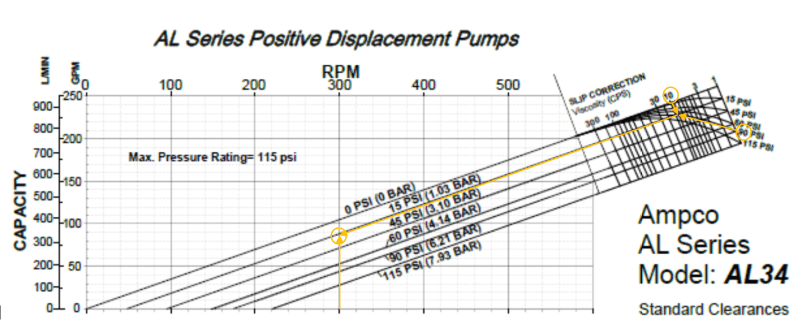
To read that chart, start at the right part - "Slip Correction". Beginning at the fluid viscosity (in your case, 1 cP), go down the mostly vertical line until your viscosity intersects with the pressure reading (15, 45, 60 psi, etc). That intersection point will lie on or between one of the main diagonal lines. Below has some arrows displaying how to read the chart. For example, running the water (1 cP) through pump at 300 rpm at 90 psig dP will result in ~45 gpm of flow. If viscosity is increased to 10 cP at the same conditions, the pump would run ~88 gpm. If viscosity stays at 1 cP, but dP increases to 115 psig due to flow restriction, flow will drop to 30 gpm.

For water, if you increase pump dP for designs that have slip, you will decrease flow rate of the pump.

Showing how to read the curve at 300 rpm, 10 cP, and 90 psig dP across the pump.
image_ieej2y.png
 
I think this pump is a little perculiar in the amount of slip. Many pd pumps won't vary by more than 5 to 10%. But look at the pump curves for any particular model.

Remember - More details = better answers
Also: If you get a response it's polite to respond to it.
 
Thank you for the explanation and responses. It really helped a long way.

Is there any simulation software that can model pump behaviour; helping you to predict these parameters under different scenarion?
 
Maybe somewhere, but usually you apply the pump curve for the model and type you've chosen.

The vendors usually supply one somewhere on their website for any specific pump.

choose the right pump from the right vendor and you should get low to no slip PD pumps.

Or get a higher capacity unit and control on flow to compensate for the increased pressure losses.

Remember - More details = better answers
Also: If you get a response it's polite to respond to it.
 
Thank you everyone for your contributions.
 
Status
Not open for further replies.

Part and Inventory Search

Sponsor