Eng-Tips is the largest engineering community on the Internet

Intelligent Work Forums for Engineering Professionals

Flow stall after pipe drops down 9

Status
Not open for further replies.

markboc

Bioengineer
Sep 1, 2020
19
0
0
DE
Hello,

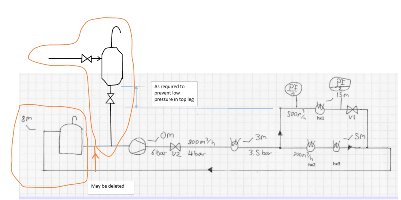
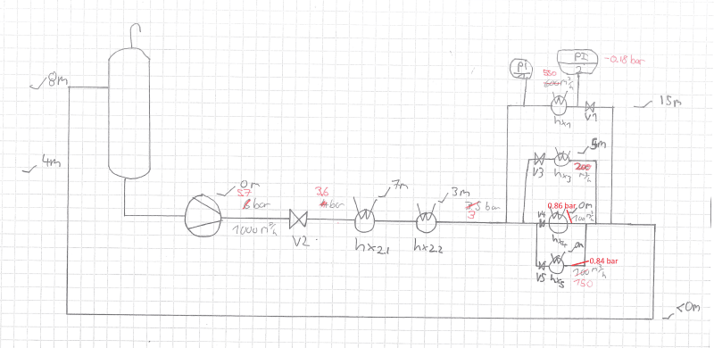
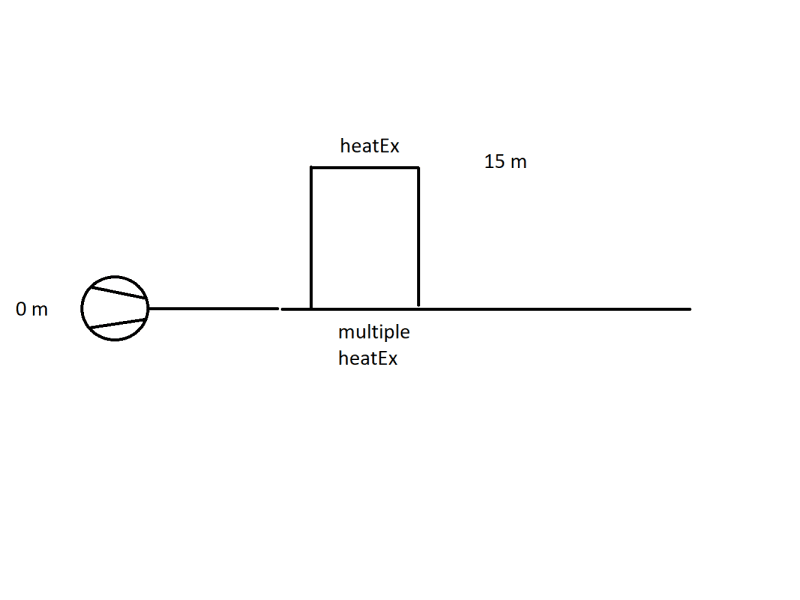
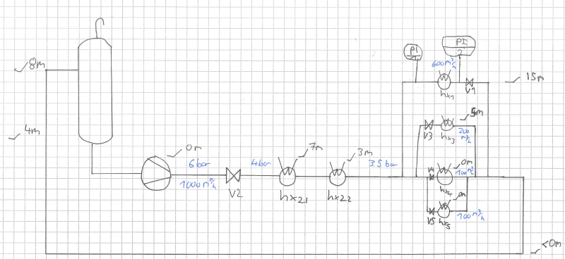
we have the following problem: A heat exchanger (15 m) is fed by a pump (0 m). It is a pipe network where other heat exchangers on parallel pipes are located much lower. The pressure gauges read low to negative pressures right before and behind the heat exchanger. Throttling behind the heat exchanger seems to solve the problem. It is suspected that the flow stalls after the heighest point of that branch of the piping system. Nonetheless the flow rate through that branch is higher than through the branch that contains the other heat exchangers, located lower.

image_w5kpc4.png


1) Can anyone direct me to literature or suitable key words for google, to get more information on the problem of the flow stalling? We suspected because the flow experiences a free fall and accelerates the vacuum in the heat exchanger is created.

2) Another mitigation which was thought of: install a throttling valve behind the pump before the pipes branches in order to increase the pressure. The increased pressure should make sure that the 15 m heat exchanger is supplied with medium. My questions here are:
2.a) The pump head matches the pressure losses of the pipe network. If I install a throttling valve the pressure will rise, but only before the valve. The increase in pressure should match the pressure drop across the valve. So in my opinion it is not possible to control the pressure in the pipe network with this method.
2.b) I am correct in assessing that the pressure at branching point does need to be greather than 15 m + pressure losses across the pipe + pressure loss across the heat exchanger. I suspect this does not pose a problem as long as the pressure loss across the other path is high enough. This would lead me to think we can ensure proper operation by throttling in the branch where the 15 m heat exchanger is NOT located.

Basically I'm trying to determine at which points we can try to control the flow in a manner, where we have no negative presssure at 15 m.

I'd appreciate your input on the situation,

have a nice weekend!
 
Replies continue below

Recommended for you

Right. And not too surprising that we still have missing info.

I hesitate to suggest adding a vent even still, because there is apparently not one there now (Markboc?), so the original designers didn't see the need for it.
I'm not sure that the pressure won't ever go higher. Unknown pump curve and other things.
And if it does take in air, is there no danger of upsetting NPSHA or air trapped at high points, if all the entrained air does not find its way out of the system at the tank.
It just seems unnecessary, at least so far, and otherwise just an additional complication.


First of all thank you all for your valuable input!

I didn't have access to my system over the weekend so I couldn't get you all the information earlier. I updated the diagram (please excuse that I mistakenly thought the Hxn were in series when they in fact were in parallel, but they are still on a separate branch from hx1, so in principle the situation shouldn't have changed).

I corrected the volume flow from 800 m^3 / h to 1000 m^3 / h, for that flow rate I have the single flows available (rounded as they were taken from a low resolution screenshot from the PCS). I also have the pressure of 4 bar available. All other pressures ( 6 bar and 3.5 bar ) are not on the PCS, hence I can't know them during the time the flow rate data was aquired. So take them with a grain of salt. Honestly I thought that this question would be more of a qualitative than quantitative nature. The possibility to get PCS info and then get the missing readings in the plant is an option and if needed I can get to that.
Especially regarding LittleInchs last remark, this would be the only option to make sure that all values correspond to each other and that a state of operation is shown that can indeed be analyzed like he tried to.

image_gbw4fx.png


I printed out the thread and marked all questions directed at me as well as possible solutions and other remarks, so I'm breaking with the tradition of quoting every user.

Your questions

Pump curve
image_hyicxv.png


Code:
0	72
72	72
139	73
217	73
294	73
362	73
421	73
511	72
607	71
710	69
793	66
852	64
934	62
1056	57
1117	54
1189	51
1222	50

Unfortunately I couldn't find much information on the heat exchangers for now. I did find out that hx1 is designed to work at 250 m^3 / h.

The control valve we were looking at should be a FCV (again, completely unsuited to achieve any pressure control other than maintaining the 4 bar). cv value is 1500 m^3 / h and DN250.

Pipe diameter is DN500 everywhere except the branches are DN200. There should be a little part after hx3-hx5 merge that is DN350 before it goes back to DN500 again. 5 m d/s of the pump is currently DN300 and it is thought of changing it to DN250 if the new V2 valve should be aquired.

The length of the common return leg is at approx. 150 m (this is the distance from the estimated union point and the pump, measured directly from an aerial image + some buffer). So I'd estimate maybe 200 m for the discharge side of the pump until union. It does not help that the return leg is underground and I don't have an isometry. Due to the age of the plant it's not unlikely that I won't get an isometry either. I talked to some people who were also looking for an isometry at some point in the past years and didn't find any, too.

I hope that answered all questions that wre asked since my last post. To answer 1503-44'S questions, I'm a german native speaker ;)

Solutions

1) Valve in common return leg
2) Vent
3) "the red valve"
4) Placing a control valve anywhere (this is what I got from one of 1503-44's posts, that the location really doesn't matter.

Currently I would prefer option 1) (and control the flow ratio with the existent valves) but I haven't had time to evaluate each solution in its entirety. Placing the red valve in combination with using the existing valves would probably achieve the same.

My questions / remarks

1) Do you mean installing a larger pipe for the download in addition to the vent?

2) With the pump curve and cv value, how would one proceed to calculate if there was any pressure increase downstream the valve? So far I've only seen that you input the pressure loss and cv and get the flow, or input the flow and pressure loss and get cv. For FCV/PCV (if I understood correctly) where either flow or pressure loss is fixed, this makes sense. But for example V2 right now is just a flap. Pressure loss and flow are not independent from one another. Would I take some flow, get the pressure loss, adjust the point on my pump curve, get the new flow and iterate until no change occurs?

3) Cascade flow cannot be tolerated as the damages at the heat exchanger cannot be tolerated or at least they don't want to aquire new heat exchangers as often as they have to now. All other Hx last longer.

4) @goutam_freelance changing or repositioning the tank is not possible.

5) @LittleInch "The data given on the sketch shows 3.5 barg, so 35m D/S of the first HX. Even allowing the additional height of 15m, 20m head loss in pipework between that point and PI1?? Doesn't make sense." give one or two days I'll try to get a current picture of the situation. Unfortunately I would also love to have more information than I currently have. Again, I was convinced the problem is of quantitative nature. As you see in the updated sketch, there should be now other chiller d/s of hx1. Hx 2.1 / Hx 2.2 seem to take away the heat. But I need to verify that tomorrow with someone and cross check the PIDs.
But now that you state it, it is strange where the pressure loss comes from. Certainly not from the 150 m of DN500 pipe.

6) "The pump should have been supplied with more head to avoid that problem entirely." you mean by throttling somewhere in the system? A larger pump with a higher head wouldn't do anything (or I am completely mistaken) because the plant dictates where I end up on the pump curve, probably at much higher flow rates then.


If I forgot to answer someones questions, please feel free to remind me again I simply must have overlooked it then.

Thanks again!
 
Now that we see that there is no heat exchanger in the common return line I am even more convinced that a simple vent at the high point is the answer. As I said before, the fact that the pressure gauge between Hx1 and V1 indicated a vacuum tells me that if this pressure is increased to 0 gauge the situation can only improve.

In case anyone thinks I am making all this stuff up, have a look at page 205 in the article by Larry L Simpson in the June 17, 1968 edition of Chemical Engineering. I didn't invent this technique - it was well known a long time ago and I just implemented it a couple of times.

With regard to your latest Question #1 - the downleg from the point A to the 8m level should be made self venting. Below the 8m level it will remain flooded with liquid and does not need to be self venting. The vent pipe can be much smaller. Probably 100 mm NB is plenty big enough.

There needs to be a valve in each heat exchanger branch for flow balancing purposes - and it appears that this is already the case. Setting the valves manually is a trial and error process because adjusting any one of the valves influences the flow in all the other branches as well. Automatic flow control through each of the branches would be great, but expensive.

The drop from Hx3 down to the common point will remain flooded because the inlet to the tank is at 8m. There will not be any vacuum created in the outlet from Hx3.

In response to the most recent post by 1503-44, there is no danger of air from the vent being trapped at high points in the return piping if the downleg from point A is designed to be self venting. The vent is not just an additional complication. It is the central piece in the solution. Without it there will always be pulsations and/or vibrations.

Katmar Software - AioFlo Pipe Hydraulics

"An undefined problem has an infinite number of solutions"
 

"V2 right now is just a flap" I'm not sure what that means. Is it a one-way flow, "check" valve?

2) Yes, hydraulically a valve is just another "flow element", exactly as is a pipe and anything else, but instead of a fixed pressure drop for a given flow, we can vary the pressure drop, provided that we can adjust its open-close position. You are right. It is just another element in the iterative solution of the "assume a flow, sum the pressure gains and losses and see if they equal the boundary conditions. If the system is a closed loop, the sum =0. If it is not closed then you must know the difference between inlet and outlet pressure and the sum should equal that difference. If not, adjust the flow.

When you model valves, first you usually assume they are fully open, then you close them, or partially close them and see how that affects your last iteration. Actually valves have a position in the range of fully open to fully closed. So if you want to look at what happens when not fully open, then we need another curve showing O/C% position vs Cv. That is important for control valves, but not too interesting for valves that are used for on/off purposes only. Those are either Cv=full, or Cv=0. Flapper check valves can often be treated the same way, as the flap moves quickly from 0 to full and the software knows that, but technically they also have a Cv vs position curve and sometimes you need to enter that data to know their specific effect of position in detail.

Pumps are analyzed in much the same manner as pipe. They are just another flow element like a pipe, except they add head for a given flow rate. Assume your flow rate and see how much head to add.

3) I do think cascade flow is best avoided, unless you have no practical alternative.
4) resolved.
5) I'm digesting that part. LittleInch?
6) A pump with a higher head potentially just gives you more pressure to work with and you don't have to deal with trying to operate equipment in or too near the "cavitation zone".

Katmar, I agree with you, 0 > -n, but I just don't see the need for it. At least not yet.

 
katmar (Chemical) said:
@bimr That might make it easier to balance the flows through the branches, but it will not eliminate the vacuum problem. The vent I have described above is the usual way to do it - and it works so well that people are not even aware that there might have been a problem.
Katmar Software - AioFlo Pipe Hydraulics

Installing a vent is more or less the same as a return leg from each heat exchanger back to the storage tank.

This installation appears to be too expensive in capital and operating costs not to conduct a complete evaluation.

markboc (Bioengineer)(OP), do you have a complete piping and instrumentation diagram (P&ID) which shows the piping and process equipment together with the instrumentation and control devices.
 
bimr said:
Installing a vent is more or less the same as a return leg from each heat exchanger back to the storage tank.

In my opinion the two options are significantly different from each other. Here are 2 important differences:

1. A 2m long vent made of 100 mm NB pipe will be vastly cheaper than 3 separate 200 mm NB return lines, each around 150 m long.
2. The vent will ensure that the pressure immediately downstream of V1 will be constant, and will be at atmospheric pressure. With a separate return line the pressure at this point will be variable and is likely to fluctuate between a positive and a negative (i.e. vacuum) gauge pressure.

Katmar Software - AioFlo Pipe Hydraulics

"An undefined problem has an infinite number of solutions"
 
OK, my take.

markboc, As I think you're realised, the key to doing anything is data and establishing that your flow diagram is actually correct. Especially if you have an old plant, drawings are just a guide as to what is actually happening out there. Where someone says there is a pressure guage is different to where it is on paper etc.

Some points from your data.

1) 1000m3/hr looks to be quite high for the pump - my guess it is is best at about 800m3/hr, but at least you're not at end of curve.
2) Running HX1 designed for 250 m3/hr at 600m3/hr is a bad idea and may be the cause of some of your issues. This will give you quite a high differential pressure but may also damage the tubes or shell in the HX itself. Needs to be checked out
3) Katmars vent pipe is interesting and after a bit of reflection I think it could be good. However it would need a clean run all the way from the union point back to the tank with no valves anyone can close. If anyone closes a valve downstream the vent then the system will pressure up with the pump running and squirt water out of your vent. but it is easy to do.

4) your point 5) is my point at the start above. Gathering data and confirming it on an existing old system which has been re configured many times and had lots of people "fiddle" with it to get it to work is 90% of the effort, but without out it nothing makes sense on the numbers you have provided. There is no substitute to literally following all the pipework on site and then drawing it up or checking against your existing drawings. Check all valves which are supposed to be fully open are fully open, any filters are clean, trace any strange junctions or connections and then you might find where the missing 2 bar / 20m head has gone.... Also check all the gauges are working properly and actually connected.

Keep us informed of progress...

Remember - More details = better answers
Also: If you get a response it's polite to respond to it.
 
Markboc said:
4) @goutam_freelance changing or repositioning the tank is not possible.

I think you misunderstood my post. I was not suggesting relocation of tank. I assume it will be quite sizeable. Instead a small expansion tank typically 2 m^3(needs calculation) can be located at an elevated level, if possible. The existing tank may be blanked off.

Below mark-up was my suggestion. We follow this type of system religiously for power plants. I hope you will not have any contradicting esoteric process requirements in your plant

image_z5gfze.png


Engineers, think what we have done to the environment !
 
What purpose does the original tank then serve?

You can't make water flow up hill.

All you're doing is turning an open system into a closed system.

Remember - More details = better answers
Also: If you get a response it's polite to respond to it.
 
katmar (Chemical) said:
In my opinion the two options are significantly different from each other. Here are 2 important differences:

1. A 2m long vent made of 100 mm NB pipe will be vastly cheaper than 3 separate 200 mm NB return lines, each around 150 m long.
2. The vent will ensure that the pressure immediately downstream of V1 will be constant, and will be at atmospheric pressure. With a separate return line the pressure at this point will be variable and is likely to fluctuate between a positive and a negative (i.e. vacuum) gauge pressure.

Don't think you understand. Your concept creates a (15 + 2) meter long vertical gravity standpipe with a gravity drain back to the tank. The reason that it will work is that you have created separate return legs. Agree that it will work but the standpipe has to be high enough so that it doesn't overflow.

Since it is now an open to the atmosphere cooling system, the owner would also have to institute a chemical treatment program to control organics and corrosion.
 
Folks, the system is already open at the tank. If they do not have a chemical treatment program already, they should have.

Good Luck,
Latexman
 
Thanks again for all the good input!

katmar said:
With regard to your latest Question #1 - the downleg from the point A to the 8m level should be made self venting. Below the 8m level it will remain flooded with liquid and does not need to be self venting. The vent pipe can be much smaller. Probably 100 mm NB is plenty big enough.
Earlier you mentioned
katmar said:
The downleg from point A to point B must be made self-venting, which would be 600 mm for a flow of 500 m3/h. [Edit]Only the section from point A down to the 8m level needs to be this larger diameter.[/Edit]
Bear with me here please, but I don't the woods from the trees.
We should install a vent like in your sketch, got that. This will raise pressure to 0 gauge and prevent the vacuum.
Then you talk about changing the leg A - B to 600 mm, and then you say 100 mm? What exactly do you mean by self venting? Getting a smaller pipe in addition to the vent? And the vent pipe can be DN100 whilst the leg gets a larger diameter of approximatly DN500 (from DN200 which it is now)?
Wouldn't adding a long/high enought small vent be sufficient if we also lower the flow rate to 250 m^3 / h as per design spec?

1503-44 said:
"V2 right now is just a flap" I'm not sure what that means. Is it a one-way flow, "check" valve?
There is also a check valve in place (omitted in the sketch) but I mean that V2 is currently of this type:
image_gt5mqs.png

This is what I meant by flap.

bimr said:
Installing a vent is more or less the same as a return leg from each heat exchanger back to the storage tank.
Adding individual legs to the tank is completely out of budget. The loop I have shown you runs through the whole plant. The storage tank is in an building. With costs of scaffolding, hundreds of metres of pipe, breaking through walls etc. this is not an option.

bimr said:
do you have a complete piping and instrumentation diagram (P&ID) which shows the piping and process equipment together with the instrumentation and control devices.
Yes, but unfortunately I cannot share these.

LittleInch said:
1000m3/hr looks to be quite high for the pump - my guess it is is best at about 800m3/hr, but at least you're not at end of curve.
Two separate flow measurements as well as the sum of the individual measurements verified operation of 1000 m^3 / h. See updated diagram at the end.

LittleInch said:
2) Running HX1 designed for 250 m3/hr at 600m3/hr is a bad idea and may be the cause of some of your issues. This will give you quite a high differential pressure but may also damage the tubes or shell in the HX itself. Needs to be checked out
At the end of this project I hope we will turn the valves at each Hx back to automatic and lower the flow.

LittleInch said:
If anyone closes a valve downstream the vent then the system will pressure up with the pump running and squirt water out of your vent. but it is easy to do.
This would add the cost of at least one DN200 pipe. I will raise this issues but I'm rather confident that a simple chain at the valves downstream will do. Usually people do not run around open / close valves as they like. We have a pretty strict work permit procedure that is to be followed. Good point nonetheless. Which brings to recognizing all the good post's here. I'll add the stars when I get to it. The response is almost too much to keep up with. But I'm grateful for that.

Regarding point 4), I went around and still missed some on site gauges (like Hx3). I cannot verify each and every point you suggested. Many places of the piping system are not easily accessed, too. But I see where you're going at.

goutam_freelance said:
I think you misunderstood my post. I was not suggesting relocation of tank. I assume it will be quite sizeable. Instead a small expansion tank typically 2 m^3(needs calculation) can be located at an elevated level, if possible. The existing tank may be blanked off.
Thank you for the clarification. I doubt that we can blank off the existing tank and go with a smaller one. I need to check but I doubt they put at tank of that size into the building without having the need for it. I take away that you want the / or a tank on the suction side of the pump in an elevated position, so you could still add it in addition to the existing tank. But since the system is inside a building this is not easily (or cheaply) done.

bimr said:
Your concept creates a (15 + 2) meter long vertical gravity standpipe with a gravity drain back to the tank.
I didn't take away that this concept introduces a separate line back to the tank. Did I misunderstand?

Latexman said:
Folks, the system is already open at the tank. If they do not have a chemical treatment program already, they should have.
The water used is DM water (VE water in german, hopefully correctly translated). If additional measures are taken I don't know. But I would suspect that such a system is in place or they would have figured that out decades ago.

And as promised I went on site today and got readings that correspond to each other. Unfortunately I missed the PI for Hx3 but I can get that tomorrow if the flow rate stayed the same.

image_zulond.png


When we get to a solution here and you are interested, subscribe to this thread so I can post an update (probably end of the year) how the solution worked out. The least I can do is to reward you with real world feedback!

edit:
1503-44 said:
This possible effect is determined by how your pump and responds to the lower flow (usually increases output pressure) and by how much pressure drop you get across V2 at the lower flow (less). You have to look at your pump curve and valve pressure-flow-position characteristics to know haw that will work, or won't work to your advantage at the heaters.
To conclude this, with the FCV valve, that keeps the pressure constant we can't achieve anything. But it _may_ be possible if we had a PCV valve, that we net gain pressure if our pump curve is appropriate. But compared to the other suggestions I don't think this would be a good option, as it depends too much on the characteristics and may not work if the pump curve and valve don't play nice together, right?

Kind regards and thanks again!
 
Last question.

What is the water level in the tank?

Could you raise it to the max to give you a slightly higher back pressure d/s HX1? You would only need 2m ABOVE the return pipe.

Your "flap" valve is normally called a butterfly valve. Flap could be misunderstood as a non return valve.

Following pipe in an old plant is sometimes very difficult alright especially when they go through walls and underground...

Only other option possible is to install a fixed orifice plate in any flange in the pipe from the union point back to the tank including the flange back into the tank. To get a relatively small pressure drop to increase the back pressure should be quite simple and a simple plate should be able to be inserted between any RF flange. And cheap...

Remember - More details = better answers
Also: If you get a response it's polite to respond to it.
 
markboc (Bioengineer)(OP) said:
Quote (bimr)
Your concept creates a (15 + 2) meter long vertical gravity standpipe with a gravity drain back to the tank.
I didn't take away that this concept introduces a separate line back to the tank. Did I misunderstand?

The existing return is a pressurized pipe:

1. If the air is removed through venting;
2. If operating with enough flow velocity to push the air out and back to the atmospheric tank.

Adding the vent at the top changes the operating scheme to a pressurized pipe to the upper heat exchanger and then it is a gravity flow return pipe downward to the atmospheric tank.

The scheme suggested by katmar has more or less created a flow scheme with separate legs (into the gravity return standpipe).

You will need some type of chemical treatment. Otherwise, the heat exchangers may foul and you will also have MIC.

 
It seems that the pump can get some flow to V1, but at the outlet pressure is less than 1 barA.
Without the vent, assume partial flow in the pipe at V1's outlet and say you only have vapor pressure, or something less than atmospheric. That pressure is driving the downstream leg flow back to the tank. Now drill a hole in the pipe and pressure increases to 1 barA and then you get more flow through the downstream leg. Or in other words, that vacuum pressure is no longer trying to suck liquid from the tank back to V1. Since you now have 1 barA at V1 and 1barA at the tank, gravity balances the downstream segment. Add a meter height of water into that segment from V1 and a meter at the other end is forced out into the tank. There is an additional friction loss there, if you do it fast
 
Status
Not open for further replies.
Back
Top