Continue to Site

Eng-Tips is the largest engineering community on the Internet

Intelligent Work Forums for Engineering Professionals

  • Congratulations KootK on being selected by the Eng-Tips community for having the most helpful posts in the forums last week. Way to Go!

Flow stall after pipe drops down 9

Status
Not open for further replies.

markboc

Bioengineer
Sep 1, 2020
19
Hello,

we have the following problem: A heat exchanger (15 m) is fed by a pump (0 m). It is a pipe network where other heat exchangers on parallel pipes are located much lower. The pressure gauges read low to negative pressures right before and behind the heat exchanger. Throttling behind the heat exchanger seems to solve the problem. It is suspected that the flow stalls after the heighest point of that branch of the piping system. Nonetheless the flow rate through that branch is higher than through the branch that contains the other heat exchangers, located lower.
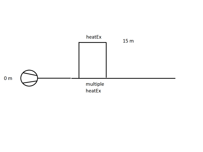
image_w5kpc4.png


1) Can anyone direct me to literature or suitable key words for google, to get more information on the problem of the flow stalling? We suspected because the flow experiences a free fall and accelerates the vacuum in the heat exchanger is created.

2) Another mitigation which was thought of: install a throttling valve behind the pump before the pipes branches in order to increase the pressure. The increased pressure should make sure that the 15 m heat exchanger is supplied with medium. My questions here are:
2.a) The pump head matches the pressure losses of the pipe network. If I install a throttling valve the pressure will rise, but only before the valve. The increase in pressure should match the pressure drop across the valve. So in my opinion it is not possible to control the pressure in the pipe network with this method.
2.b) I am correct in assessing that the pressure at branching point does need to be greather than 15 m + pressure losses across the pipe + pressure loss across the heat exchanger. I suspect this does not pose a problem as long as the pressure loss across the other path is high enough. This would lead me to think we can ensure proper operation by throttling in the branch where the 15 m heat exchanger is NOT located.

Basically I'm trying to determine at which points we can try to control the flow in a manner, where we have no negative presssure at 15 m.

I'd appreciate your input on the situation,

have a nice weekend!
 
Replies continue below

Recommended for you

Thanks, I'm not sure I agree with that; I had thought that the flow through the other exchangers created a Venturi effect at the T, where the flow is sucking air and water from the downstream side of hx1, slightly reducing the head on the upstream side of hx1, allowing it to work sometimes.

TTFN (ta ta for now)
I can do absolutely anything. I'm an expert! faq731-376 forum1529 Entire Forum list
 
I'm pretty sure they are just trying to run over original capacity, so they are winding up with low low pressure at the highest HX. Happens all the time in old plants. I might try do a proper model of it. Maybe enough data already to start. I can probably bracket it in for now.

 
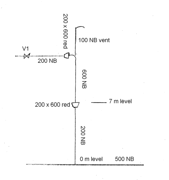
With the latest information I am very confident that the vent system will work well. If there is a flow of 1000 m[sup]3[/sup]/h in the return line and it has an equivalent length of 200 m of 500 NB pipe the friction pressure drop from the commoning point back to the tank will be less than 0.1 bar. The measured pressure at the commoning point is 0.84 bar and the tank return height is approx 8 m. This all ties together very well and indicates that the water will not back up into the vent.

If the pressure at the base of the downleg from Hx1 is 0.84 bar then the downleg cannot be liquid filled to the 15 m level as that would result in a 1.5 bar pressure at the base. The downleg will be liquid filled to approximately the 8.4 m level and above that will be filled with vapor. At present there is no way for vapor to enter that space so it is created by the boiling of the liquid. This boiling is partly what causes the vibration and resultant physical damage. Putting a vent at the top of the downleg allows air to enter and fill the space that is required to be vapor filled. As the flow rate through the heat exchangers varies the pressure required to return the water to the tank will also vary, and so the level in the downleg will vary and the vapor space can breathe air in or out through the vent to compensate.

The air flow through the vent is very low. Describing it as breathing is quite accurate. A 100 mm NB pipe will be large enough, although it could be even smaller if it does not have to be self supporting.

The upper 6 or 7 m of the downleg will be air filled and there will be water from Hx1/V1 falling through it. The water will entrain air and if steps are not taken to allow the air to be de-entrained it will be carried into the return piping and cause problems. This de-entrainment of the air is called self-venting and it is achieved by keeping the Froude Number below 0.3. There are plenty of discussions on Eng-Tips on the Froude Number and the design of self-venting pipe and I won't go into it here. But what it means is that where there can be air and water together the pipe diameter must be larger. About 1 m of depth is required below the liquid level in the downleg to achieve the separation of the air. This means that the section of the downleg above 7 m should be self venting and the lower section can be designed purely on frictional pressure drop.

This is shown in the sketch below
Pump_Circuit4_qejc21.gif


The flap valve for which you included a picture is called a butterfly valve in English (Absperrklappe in German).


Katmar Software - AioFlo Pipe Hydraulics

"An undefined problem has an infinite number of solutions"
 
Sorry for delayed response! I was preoccupied with other projects.

LittleInch said:
What is the water level in the tank?
Could you raise it to the max to give you a slightly higher back pressure d/s HX1? You would only need 2m ABOVE the return pipe.
Above what return pipe? I could see if we have a LI for the tank (probably).


LittleInch said:
Only other option possible is to install a fixed orifice plate in any flange in the pipe from the union point back to the tank including the flange back into the
This was also one of the original ideas but to be flexible with changing operating conditions and the fact that the time frames in which can work on the pipe are scarce, we would prefer valves.

bimr said:
How is the heat energy being removed from this system.
LittleInch is correct, I mentioned it earlier in a post. hx2,1 and hx2,2 do remove the heat.

1503-44 said:
so they are winding up with low low pressure at the highest HX. Happens all the time in old plants. I might try do a proper model of it. Maybe enough data already to start. I can probably bracket it in for now.
Happens all time in old plants: I'm pretty confident we run into the same caveats as other older plants.
If doing a model is not too much work for you this would be greatly appreciated! I'm already grateful for the time you and the others spent on this thread / problem.


Thank you katmar for the clear explanation!

I will keep you posted on the progress.
 
Sure Mark. I started setting up a basic system. I could use some approximate pipe lengths between all devices and temperatures of water at the pump and hopefully going into and out of the HXs. Are the pipes insulated? I stopped, because you disappeared for awhile. Now that you are apparently alive and well, and interested in continuing, I'll start filling in the remaining bytes.

 
Thank you very much!

We're currently in the construction phase of other projects and that consumes quite a bit of my days currently. So bear with me if my response times are a little bit slower than usual.

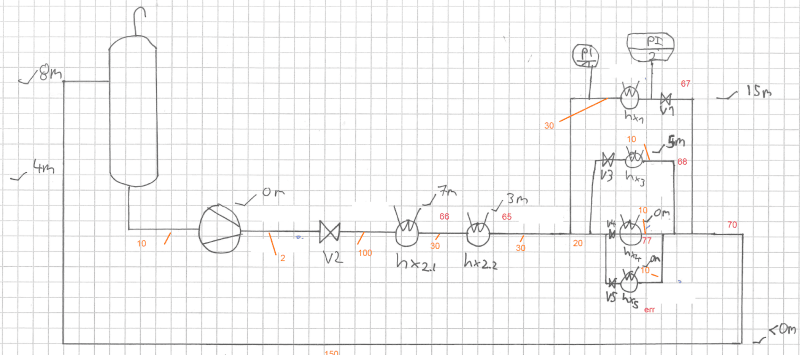
Orange = Distance in m
Red = Temperature in °C

image_ytnfyl.png


The lengths are rough estimates, the temperatures correspond to the flow rates and pressures of my latest update.
 
OK. Me too.

I'll start with that and let you know here as soon as I have something to tell you.
 
Would not be a good idea to add another pump for the upper heat exchanger line only for the required pressure and flow after the tee connection since the pressure loss and head are major problem for this line?
 
mark,

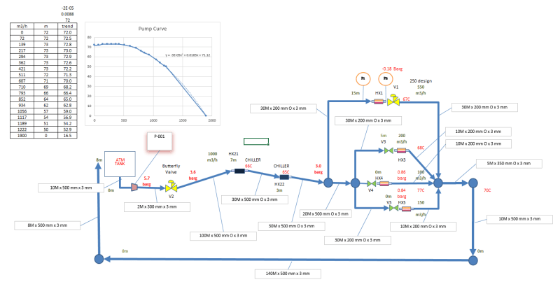
I went back through all the postings above scraping data and made this diagram of what I think the system looks like.
Is the bottom of tank at 4m elevation?

It would help if you could check my diagram for proper configuration and data values.
MARKBOC_PFD_xgcedg.png

Thanks
 
Mark, Do you have the pump's rating parameters at BEP and driver's max power?
BEP RPM
BEP HEAD
BEP FLOW
BEP POWER
DRIVER POWER RATING

How old is this system?
 
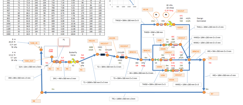
Mark, Built a model that seems to correspond reasonably well with the info above.
Checking water @70°C, vapor press is 31kPa_A and all pressures are higher, so no indication of cavitation. Are exchanger damages erosive? That will occur with high velocities.

Markboc_PDF_rev_1_vhikem.png


Report: HEADERS
Device kPag-in kPag-out Qm3/h
------ -- -- --
S1H 39.000 76.529 1075.595
DH1 596.671 594.847 1075.595
HX21 405.553 370.845 1075.595
HX22 407.820 373.204 1075.595

HX1 225.041 -17.827 540.705
HX3 344.746 45.444 236.907

HHX31 45.444 91.000 236.907
H4 400.705 398.842 534.890
HX4 398.796 91.473 120.032
HHX41 91.473 91.000 120.032
HX5 395.052 92.039 177.951
HHX51 92.039 91.000 177.951
HR1 91.000 90.934 1075.594
HR2 90.934 90.602 1075.594
HR3 85.986 10.000 1075.595

Report: TRANSFER_LINES
Device kPag-in kPag-out Qm3/h vel m/s VaporPress kPa_A
------ -- -- -- -- ---
T1 405.553 475.119 1075.595 1.639 30.524
T2 407.820 370.845 1075.595 1.634 25.549
T3 400.705 373.204 1075.595 1.633 24.434
THX10 225.041 400.705 540.705 5.462 24.434
THX11 91.000 -18.031 540.705 5.470 26.720
THX30 344.836 398.842 236.907 2.393 24.434
THX50 395.119 398.842 177.951 1.798 24.436
TR1 85.986 90.602 1075.595 1.639 30.456
 
Using V1 as a control valve,

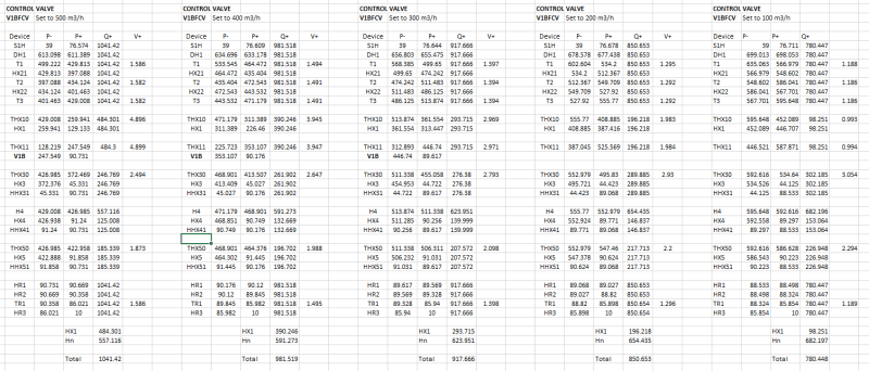
Lowering Flowrate settings at V1.
you can lower the flow through HX1 from 600m3/h down to 210m3/hr.
Unstable flow begins at 210m3/h and reaches severe levels at 200.
Flow at 200 will not stabilise. V1 discharge pressure is within 20 kPa of vapor pressure.
Probable downstream vaporization with vapor pocket collapse generating transient pressure waves that affect the valve and HX1 exchanger.
Decreasing flow into the 190 to 140m3/h range takes time to reach stability, but eventually those flow rates will stabilise. Best not to operate in that range.
130 m3/h is more stable, but takes a short time. Pump flow is 800m3/h.
80 m3/h and lower to 0 are more stable. Pump flow is 767m3/h to 709m3/h.

Raising Flowrate Settings at V1.
Raising flow through HX1 shows signs of unstable flow at 140 to 150m3/h
Other flow rate settings appear to be stable.
 
What does your model say if V1 is moved from immediately downstream of HX1 and rather placed at the bottom of the downleg near the combining point. I don't think it would be as stable as using a vent at the 15 m level, but it should give better stability than where it is now.

Katmar Software - AioFlo Pipe Hydraulics

"An undefined problem has an infinite number of solutions"
 
Patience please?
It should be very stable with another 15m of head on it.
 
I improved the stability of the previous runs with V1 as a control valve by reducing the PID gain and slowing down the actuator a lot, but there are still indications of instabilities at 200 and 500m3/h through HX1. You could rig V1 as a control valve, if you have to.

A control valve placed just before the intersection at "BRANCH3" works very well.
There is some instability when set to 400m3/h, but it soon settles out.
The control valve's PID is getting its input signal by reading flow at HX1.
If you can't put a FIT there, I think it can be set up as a PCV, but I didn't look into that.

I ran the model a number of times dropping the control valve's flow set point by 100 m3/h each time with the following results.
The valve controls the flow to HX1 according to its set point and all remaining flow from the pump is diverted to the HX3,4 & 5 group. You can see the approximate flow rates entering each HXn branch. If you do not need other flow distributions to those HX3,4 & 5 heaters, then you're done. If a finer control on flow to the heaters in that group is needed, I would suggest adding 1 control valve to each of two heaters, set those to the required flow rates and let the third heater carry the remaining flow. The total flow distributed to the HX3,4 & 5 heater group will be whatever is not going to HX1. You could redistribute that to this group as you choose with the two additional control valves. A third valve could be used, but it will not give you additional control as you might think. If you have 2 valves partially closed and partially close a third valve (without backing off one of the first two), all that will happen is the "equivalent pressure drop" in this group will rise higher than needed and that will actually start diverting some flow from this group back over to HX1. Then the flow controller sees the flow trying to increase, so it begins to close some more, which just results in a pressure back up on the pump curve. That tends to increase pressure at a lesser flow rate. If you do put valves on all 3, just keep one of them fully open.

Results_Rev0_tgqnr1.png
 
1503-44 said:
Is the bottom of tank at 4m elevation?
Yes.

1503-44 said:
How old is this system?
From what I gathered from the documents, the pump is from 1980.

1503-44 said:
Mark, Do you have the pump's rating parameters at BEP and driver's max power?
RPM 1480, not sure if it's BEP but it's 85 % efficiency: head 60 m, Q 1050 m^3/h, power 195 kW (rated 260 kW)

1503-44 said:
Mark, Built a model that seems to correspond reasonably well with the info above.
Thank you very much, again, greatly appreciated!

1503-44 said:
Are exchanger damages erosive? That will occur with high velocities.
I'd need to check that, at first glance even at 550 m^3 / h I wouldn't think of that. Unfortunately I don't have access to the documentation remotely right now.

1503-44 said:
Checking water @70°C, vapor press is 31kPa_A and all pressures are higher [...] HX1 225.041 -17.827 540.705
Is this actually the output of your model? I'm surprised because the -17.827 do seem to fit the real world reading perfectly. I'm just confused because you came to the conclusion that all pressures are sufficiently high.

and now in response to your calculations / findings in general:

With instabilities you mean the flow does not stabilize in the sense of a constant flow rate but varies rather. You are not talking about partial flow but about the instability in the sense of control systems?
I'm totally with you that it's best to not use the last control valve rather than diverting all other flow through the hx without the valve.
Am I correct in assuming that if an overall lower heat exchange (during winter or different demands in the plant in general) is needed, additionally regulating the overall flow rate with V2 (or a FCV there) would be possible?
It's really awesome to be able to pin numbers to the different scenarios! From your data alone I would even say that V1 is enough at this point and using two additional FCVs for hx3 and hx4 for example would just be the icing on the cake. The flow rates do seem to be well within the specifications of the heat exchangers.

Which software did you use to make these calculations?

Did you also consider the case where V2 (or an additional valve) is placed in the common return leg?

@katmar since a vent is tied to a lower invest we are still investigating that route as well.

Have a nice weekend!


I entered water's vapor pressure curve into the model. I set pressure drops through the HX's to match what you told me at your flow rates and the program calculates proportional drops to match velocities of all other flow rates I wanted to run. I entered your pump curve too. I just guessed and set the wall thickness of the pipes at 5mm.

Yes the instabilities were the result of the control configuration for V1. At first I had a fast acting valve with a high gain used in the PID controller. It caused the valve to react too quickly on slight flow deviations, closing too much and allowing pressure to drop below vapor pressure and then rise above. When the vapor pocket collapses, pressure waves were created that affected the flow rate and started the controller cycling again. Slowing the valve down solved almost all of that. Moving V1 to 0m elevation helped a lot. 400m3/h cycles some, but it stabilises quickly now.

I did not try any scenarios using other valves, or even activating V2, as there seems to be a lot of flexibility of making just about any flow rate you want already with V1 alone. Adjusting V2 to a new flow rate will change all the flows above proportionally, so there is also considerable redundancy present. If you need to proportion the flow going into the HX 3, 4 & 5 group differently, then right, just add some more valves in there.

The simulation shows that the system as is can be operated in a manner that there is enough pressure to stay above the vapor pressure. That does not mean it is being operated that way. And if flow deviations are not being responded to quickly and being properly controlled, the instabilities I observed might persist long enough to some damage. I have no info about that. It is apparent that a careful hand is required to keep V1 properly adjusted in the system with its present configuration. What could seem like minor uncontrolled changes in flow rates may have a significant negative effect on HX1.

I believe that moving V1 to near 0m elevation will make control easier and result in a more stable operation at all flow rates within the design operating range of the equipment. Of course if those ranges are exceeded, all bets are off. Flow rates higher than the maximum case above will lower the pressure further, which will eventually get near or lower than vapor pressure at HX1. Keeping flow low enough so that the pump is operating at higher points on its curve and giving sufficient pressure to stay above vapor pressures at HX1 is important. Holding pressure there to 0 kPag would be the equivalent of Katmar's drilling a hole there solution, albeit more costly ... I suppose. But maybe not if the pipe diameter has to be increased???

Rather than have flow rate control for V1, a pressure control might provide a more secure means to avoid low pressure at HX1. V1 could be controlled to adjust its open/close position to keep HX1 pressure always sufficiently above vapor pressure, ie. set to -15 to zero kPa. The flow rate would automatically reduce to correspond to that set pressure. More info about how production operations uses HX1 and how they would like to control the flow rate into it is needed.

The program I used is a precursor to this one currently offered in DNV's lineup. Actually it was the first program written for dynamic simulation of piped fluids. I've been using versions of the same program since when I had to send and receive telex files to/from a mainframe in Pennsylvania in 1986. I actually did some client partnership work with the original program owners and wrote the code for their ActiveX based graphic displays to model tanks. Before that they could not graphically display liquids in a tank! That's often quite important for oil pipeline operation simulations.
 
All participants have certainly given their keyboards a hard workout? Considering Hx1 is 15m above the pump (and other Hx's) I dont see any means of venting the line running up to Hx1. Essentially it is the high point in the system and will trap and air/vapour, thereby reducing the pipe diameter, increasing velocity, creating turbulence, and rendering the Hx less efficient.
 
I'm not going to re-read the whole thread, but I do not recall anyone suggesting installing a vent before HX1. There is no reason for air to be in the system upstream of HX1 and no venting is required there. The vent is required at the top of the downleg after HX1.

Katmar Software - AioFlo Pipe Hydraulics

"An undefined problem has an infinite number of solutions"
 
I'm not suggesting a permanent vent. A 1/2 inch ball valve at the highest point. When putting the system into operation vent any air that accumulates at the highest point, close it off and forget about it. Considering it's a closed loop system, once it has been vented on start up there should be no further accumulation of air.
 
Status
Not open for further replies.

Part and Inventory Search

Sponsor