Hello,
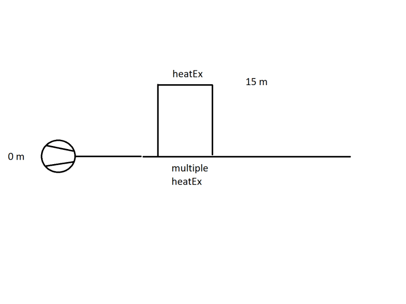
we have the following problem: A heat exchanger (15 m) is fed by a pump (0 m). It is a pipe network where other heat exchangers on parallel pipes are located much lower. The pressure gauges read low to negative pressures right before and behind the heat exchanger. Throttling behind the heat exchanger seems to solve the problem. It is suspected that the flow stalls after the heighest point of that branch of the piping system. Nonetheless the flow rate through that branch is higher than through the branch that contains the other heat exchangers, located lower.

1) Can anyone direct me to literature or suitable key words for google, to get more information on the problem of the flow stalling? We suspected because the flow experiences a free fall and accelerates the vacuum in the heat exchanger is created.
2) Another mitigation which was thought of: install a throttling valve behind the pump before the pipes branches in order to increase the pressure. The increased pressure should make sure that the 15 m heat exchanger is supplied with medium. My questions here are:
2.a) The pump head matches the pressure losses of the pipe network. If I install a throttling valve the pressure will rise, but only before the valve. The increase in pressure should match the pressure drop across the valve. So in my opinion it is not possible to control the pressure in the pipe network with this method.
2.b) I am correct in assessing that the pressure at branching point does need to be greather than 15 m + pressure losses across the pipe + pressure loss across the heat exchanger. I suspect this does not pose a problem as long as the pressure loss across the other path is high enough. This would lead me to think we can ensure proper operation by throttling in the branch where the 15 m heat exchanger is NOT located.
Basically I'm trying to determine at which points we can try to control the flow in a manner, where we have no negative presssure at 15 m.
I'd appreciate your input on the situation,
have a nice weekend!
we have the following problem: A heat exchanger (15 m) is fed by a pump (0 m). It is a pipe network where other heat exchangers on parallel pipes are located much lower. The pressure gauges read low to negative pressures right before and behind the heat exchanger. Throttling behind the heat exchanger seems to solve the problem. It is suspected that the flow stalls after the heighest point of that branch of the piping system. Nonetheless the flow rate through that branch is higher than through the branch that contains the other heat exchangers, located lower.

1) Can anyone direct me to literature or suitable key words for google, to get more information on the problem of the flow stalling? We suspected because the flow experiences a free fall and accelerates the vacuum in the heat exchanger is created.
2) Another mitigation which was thought of: install a throttling valve behind the pump before the pipes branches in order to increase the pressure. The increased pressure should make sure that the 15 m heat exchanger is supplied with medium. My questions here are:
2.a) The pump head matches the pressure losses of the pipe network. If I install a throttling valve the pressure will rise, but only before the valve. The increase in pressure should match the pressure drop across the valve. So in my opinion it is not possible to control the pressure in the pipe network with this method.
2.b) I am correct in assessing that the pressure at branching point does need to be greather than 15 m + pressure losses across the pipe + pressure loss across the heat exchanger. I suspect this does not pose a problem as long as the pressure loss across the other path is high enough. This would lead me to think we can ensure proper operation by throttling in the branch where the 15 m heat exchanger is NOT located.
Basically I'm trying to determine at which points we can try to control the flow in a manner, where we have no negative presssure at 15 m.
I'd appreciate your input on the situation,
have a nice weekend!

![[cheers] [cheers] [cheers]](/data/assets/smilies/cheers.gif)