Continue to Site

Eng-Tips is the largest engineering community on the Internet

Intelligent Work Forums for Engineering Professionals

  • Congratulations pierreick on being selected by the Eng-Tips community for having the most helpful posts in the forums last week. Way to Go!

Foundation loads of Vertical Vessel/HEx Lugs on Supporting Structure 1

DeathRay009

Mechanical
Jan 7, 2024
22
Hi all,
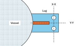
We are in the process of ordering a Heat Exchanger. The heat exchanger is vertical and supported by two lug supports. The vendor has given us a foundation loads table. In this table the vendor has mention wind/earthquake shear and wind/earthquake moment.

I understand how the shear forces are calculated and how they will be transferred to the foundation, But I can't get my head around how the wind/EQ moment load is calculated and how it will be transferred to the foundation (since the lugs are attached to the steel structure using two bolts/lug, so that the connection is considered pinned).

Your help will be of great value in this regard.
 
Replies continue below

Recommended for you

Probably just an overall moment calculated by multiplying reaction force by distance from COG
 
Probably just an overall moment calculated by multiplying reaction force by distance from COG
So if I am designing a foundation should I calculate the forces from moments and then design the foundations as per that?
 
It is not clear how the support is configured. You appear to be saying that the lugs on the vessel are attached to the steel beam/member which it is supported from using bolted connection? Are the structual supports then attached to a foundation? If so why would these be pinned connections? This connection can take moments developed by horizontal wind and seismic loads.

The wind and earthquake forces acting on the vessel will create rotational moment on the overall vessel. For a vessel supported by lugs on opposite sides, the moment will be transferred to the steel support by a up and down force couple which produces a counter moment equal to the wind/seismic moment on the vessel. In addition there will be a horizontal shear at each lug equal to the total wind/seismic force divided by 2. And a downward force at each lug equal to the weight of the vessel divided by 2. All these loads are then need to be transferred to the connection points of the steel structure to the foundation. For instance horizontal shear at the lugs will cause a moment on the foundation assuming the location of the lugs/steel is elevated above the foundation.

I would check the loads they gave you using ASCE 7 methods for wind and earthquake.
 
Last edited:
I'm not familiar with designing foundation, but if you consider that the lug are pinned to the ground, then you consider that moments wont be transfered at all to the foundation and will only be sustained by the beams/lugs. In this configuration i don't see why you should design foundation to resist the moments. Again just an opinion i'm not an expert
 
It is not clear how your structure is configured. You state lugs pinned to the ground and also state "sustained by beams/lugs". How can the lugs be both pinned to the ground and supported on beams. Is there an elevated structural steel support which the vessel with lug is placed on which in turn is placed on a concrete foundation or is the lugs supported directly on the foundation. Need sketch.
 
It is not clear how your structure is configured. You state lugs pinned to the ground and also state "sustained by beams/lugs". How can the lugs be both pinned to the ground and supported on beams. Is there an elevated structural steel support which the vessel with lug is placed on which in turn is placed on a concrete foundation or is the lugs supported directly on the foundation. Need skTh
The lugs are placed on beams of an existing steel structure, The structure is attached to concrete foundations with full moment connections.
 
Are the structual supports then attached to a foundation?
The lugs are placed on beams of an existing steel structure, The structure is attached to concrete foundations with full moment connections.
If so why would these be pinned connections?
I am saying that the lug to beam connection is pinned considering it only has two bolts per lug in a straight line
This connection can take moments developed by horizontal wind and seismic loads.

The wind and earthquake forces acting on the vessel will create rotational moment on the overall vessel. For a vessel supported by lugs on opposite sides, the moment will be transferred to the steel support by a up and down force couple which produces a counter moment equal to the wind/seismic moment on the vessel.
Yes, I get that but the loads for which the beam will have to be designed will only be forces not moments right? Thats what I am trying to confirm, when moment on vessel is parrallel to Y-Y then we will get a moment in the beam support the lug, however when the moment is parrallel to X-X then the moment can be resolved into force couple. Thats what I have think will happen.

Plus can I please find somewhere a solved example related to this(where they calculate the foundation loads or loads transmitted by lugs to supporting structure) for my learning?
 

Attachments

  • Screenshot 2025-01-25 220621.png
    Screenshot 2025-01-25 220621.png
    38.4 KB · Views: 3
Yes, I get that but the loads for which the beam will have to be designed will only be forces not moments right? Thats what I am trying to confirm, when moment on vessel is parrallel to Y-Y then we will get a moment in the beam support the lug, however when the moment is parrallel to X-X then the moment can be resolved into force couple. Thats what I have think will happen.

If the force causing the moment was parallel to the y-y axis then the moment would be resolved into a force couple, consisting of one down force and one up force, on each lug. If the force causing the moment was parallel to the x-x axis a torsional moment will be felt by the lugs which will be resisted by one of the bolts of the lug in tension (up) plus force of the bearing load of the lug plate on the beam. This puts a moment on the beam.

I will check my pressure vessel reference books to see if they have an example calculation.
 
More data; PV diameter / length, material, pressure & temperature, location of supports, type of heat exchanger TEMA,
Two supports?

Is it so difficult to draw a picture?
 
Here is a vessel lug design from Pressure Vessel Design Handbook, 2nd Edition, Henry H. Bednar. If you enlarge and rotate properly you should be able to see everything. If not let me know if you need another copy of anything. One more post to follow with another reference.
 

Attachments

  • IMG_2204.zip
    5.9 MB · Views: 9
Here is a vessel lug design from Pressure Vessel Design Manual, 3rd edition, Dennis Moss. It is a very popular reference book. This book is a little hard to follow as they don't provide complete explanation of exactly how to perform the calculations but you should be able to follow.
 

Attachments

  • IMG_2211.zip
    14.1 MB · Views: 5

Part and Inventory Search

Sponsor