Continue to Site

Eng-Tips is the largest engineering community on the Internet

Intelligent Work Forums for Engineering Professionals

  • Congratulations KootK on being selected by the Eng-Tips community for having the most helpful posts in the forums last week. Way to Go!

GD&T Datums from two Holes

Status
Not open for further replies.

Brokenengineer

Mechanical
Jul 1, 2021
15
Hi all,

I was hoping if someone could review my use of Datums and FCFs in this example sketch. I am creating a production drawing for a part, and will be applying a GD&T scheme similar to this. But this is one of my first formal uses of GD&T,
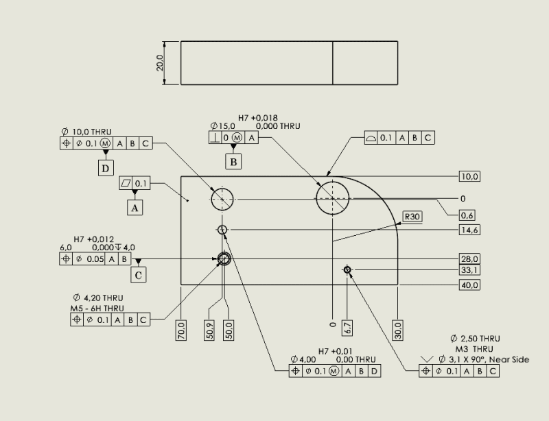
image001_q1tczn.png


To understand design intent: The 15mm hole aligns with the centre axis of a mating disc. The 6mm hole is used to align a detent to rotationally align the disc. The other features are items that interact at certain points on the disc.

My main questions are:
Is the use of datum A and B sufficient to position the Hole used for Datum C?

Can all other features then reference ABC as Datums?

Have I used the MMC correctly?

Is the outer profile FCF used correctly?

Please see attach image. Also I know the sketch is not drawn well, but I put this together in a rush.

Many thanks for your help! I am in in the process of booking a GD&T course with my company but this drawing needs to go out within a few weeks.

 
Replies continue below

Recommended for you

It doesn't look bad - the only possibly missing FCF item is the All Around symbol for the profile tolerance; either that or use more profile tolerances on the other perimeter surfaces.

The 10mm hole is missing a diameter tolerance and the thickness is missing a tolerance as well.

Aside from the All Around on the Profile tolerance I'd say yes to your questions. It seems drawn well enough.
 
Hi Dave, thanks for the feedback!

I will add the all around symbol!
We use a standard tolerance table dependant on decimals, hence why no tolerance on some dims. But yes point taken.

 
What would be the tolerance of the thickness of the part? 20,0? There is a reason I am asking because your flatness of 0.1 could be redundant depending this tolerance.
 
Thickness is 20 +-0.1.

And isn't flatness independent of thickness.
I.e. you can have sheet metal of 3mm +- 0.1 thickness and then roll it to a radius of 100mm, It would not longer be flat but thickness is still 3+-0.1
 
brokenengineer said:
Thickness is 20 +-0.1.

And isn't flatness independent of thickness.
I.e. you can have sheet metal of 3mm +- 0.1 thickness and then roll it to a radius of 100mm, It would not longer be flat but thickness is still 3+-0.1

First of all: what standard dimensioning and tolerancing are you using? I read this discussion and does not say anywhere.
 
Hey Greenimi,

Out drafting standard is BS8888 so the drawing should be to ISO GD&T,

Sorry I cut out the company title block.

Thanks
 
EDIT - Sorry, just noticed that you are using ISO and not ASME. I am not very familiar with ISO but maybe some of the below still applies.

for standard compliance:
The perpendicularity FCF is missing a dia. symbol in front of the zero tolerance value.

for clarity:
Add the all around symbol to the profile FCF.

for consistency:
Put the Datum Feature Symbol for "C" tagged to the FCF of the 6.0 hole.

unsolicited input:
1) Depending upon the design intent of this part you could apply Flatness of the Derived Median Plane instead of surface flatness. If you assign MMC bonus tolerance to the FDMP than you could use a pass through gage to check the flatness of the part. This is an inexpensive gage and may make inspection of flatness easier. Again, this is assuming that FDMP (w/ MMC bonus) aligns with the design intent of the part. See ASME Y14.-2009 section 5.4.2.1 Appplication of Flatness RFS, MMC, or LMC to Noncylindrical Features.

2) How do you intend to verify the position of the threaded holes? Consider adding MMC bonus tolerance and projecting the tolerance zone to the mating side of the part. See ASME Y14.-5 2009 section 7.4.1 Projected Tolerance Zone.
 
You might also want to consider using the MMC modifier in the position tolerances for the two threaded holes. It's not required, but ask yourself how it would be measured without the MMC modifier (an expanding thread gage?).

EDIT: Sorry AndrewTT... I thought I read all of the comments, but I guess I overlooked your last line!
 
ISO definition is a game changer then.
I am thinking that if you use all around symbol for the profile (as recomended above) a collection plane indicator should also be shown.
By the same token, maybe some CZ's or SIM's are needed for the functional needs (to "replace" and enforce the default simultaneous requirements)
 
Collection planes shall be used when the “all around” symbol is applied. The collection plane identifies a family of parallel planes, which identifies the features covered by the “all around” indication.

 
Interesting about collection planes. ISO must be ditching the concept for order of application of the DRF references(Sorry) datum systems for some reason. I can see where the ASME guys get their inspiration. This requirement appears to be new to the 2017 version.

 
Also - need to specify if the profile tolerance is EZ, CZ, or UF! And don't forget, CZ and SZ are to be specified in the collection plane block, but UF is not.
 
Hi all,

Thanks for you comments, definitely a bit out of my depth now, but its good to learn.

Just replying to some points in order:


[li]DMPF doesn't apply to our design intent. We require the face to act a sealing face.

I haven't used projected tolerance zones before. I sort of understand the principle. But I'm unclear how it helps functionally. Is the idea of using MMC and projected tolerance zone such that you can screw in pin guage and then use a CMM to measure the position? Would adding the 'Minor Dia' modifier meet an equivalent purpose?

If i used MMC for the threaded holes, how does this allow me to measure it better? I thought flexible thread gauges were standard.

I haven't heard of collection planes before... Am I not allowed to use the all around symbol in ISO GD&T? I tried a quick Google but couldn't find Anything about collection planes. I need to read that PDF in some detail this weekend...

But from a basic understanding I think I just need to add CZ to the profile FCF..?[/li]


It depends on which version of the standard you are using as to whether collection planes are required. ISO changed the rules for profile in 2017.

Just for amusement - I totaled up what appear to be the set of ISO GPS documents one would require to be competent: It appears to be over $3700 for the set. Those ISO guys are truly inspired. I admit that I'm not spending over $2000 to figure out if the next $1700 are required, but splitting bunches of basic documents into Part 1 and Part 2 at $60 or so each up to $200 solely for datums? Priceless.
 
Brokenengineer said:
If i used MMC for the threaded holes, how does this allow me to measure it better? I thought flexible thread gauges were standard.

If you use an MMC you allow the use of fixed size thread gages, which allows a bit of clearance between the female thread and the gage (the gage is supposed to be at the MMC pitch diameter of the thread). This may be very slightly less restrictive than Regardless Feature Size as a requirement, and a bit more functionally representative of the application.
 
Been discussed here many times:
* make a split threaded feature with a taper to expand it for RFS. available from several sources
* split threaded gages are still far too expensive for most uses.
* The Bryce paper is gone from the original site. This may be similar:
(PowerPoint, missing Conclusion)
reference work: * Another source of expensive MMC gage threads; they appear to force perpendicularity with the surrounding surface. * The pitch diameter is not where threads make contact; it may be where they also make contact. They nominally make contact on the full helical surface where they overlap on installation. Consider, for example, the case of the square thread. It remains self centering by the helical face and everywhere that face is made of elements that are nominally perpendicular to the nominal axis of the thread. The PD is chosen as a polite fictional stand-in for the remainder of the spiral face because one can use pins and a micrometer to establish an approximation for its diameter on external features, simplifying the job for the inspector while sacrificing the knowledge of the condition of all elements of the thread contact.
*
MechNorth said:
There have been many studies conducted by national labs in the USA & around the world re the repeatability and accuracy differences associated with inspection of thread position based on the pitch, minor and major diameters. They (national labs) can't replicate their own results for the same setup within very tight tolerances.
 
Here is another observation.
One popular opinion is that MMC shouldn't be used on threaded holes because the bonus tolerance that is available is very small. I personally don't think it's a good argument because the fact that only a very small amount of good parts can be spared from being rejected doesn't mean the designer should not allow the possibility of accepting these parts.

The question is ISO related, but in the ASME world what I find to be the more concerning thing about threaded holes controlled with an MMC modifier is that the standardized concept of Virtual Condition as applied to internal features does not apply to it (at least not the same way it applies to clearance holes). The ASME Y14.5 standard for sure fails to document it (except for a hint in the appendix which is the Fixed Fastener formula and the idea behind it). And that is despite showing only MMC examples of position tolerances on threaded holes.
I wonder - does ISO treat it any better?
 
I am maybe more confused about threaded holes than to begin with... [dazed]

From what i understand, if i specify a True Pos. tol on a threaded hole callout:

I am specifying the true position of the centreline of the Pitch Diameter. This is effectively an immearsurable feature. But flexible thread gauges are the best known way to measure this.
Adding the MMC to the specification validates the use of a flexiable thread gauge a bit more as it includes the bonus tolerance.
Depending on tolerance zone, fixed thread gauges may be used but the likelihood of this fixed gauge sitting on the ture PD centreline is less than the flexible gauge.
Then an alternate measurement is of the Minor Diameter of the Threaded hole, which is almost certainly not on the centreline of the PD, but to what degree is based on if the thread was cut in the same machining operation.

However, none of these statements are quantified... does anyone know if there is any data on the expected error of measurement for each of these methods?

This website seemed quite useful, but maybe someone with some more experience can valiadate its information.
Additionally I am still slightly unclear how the projected tolerance zone is measured for a threaded hole. Could someone explain this? I assume its based on the same types of gauges as above, so the true PD centreline is still effectively unkown...


As an example would the tolerances on the M3 hole in my original image above be suitable for using a fixed thread position gauge on a CMM?
 
Status
Not open for further replies.

Part and Inventory Search

Sponsor