Eng-Tips is the largest engineering community on the Internet

Intelligent Work Forums for Engineering Professionals

GD&T: How to inspect tertiary datum feature position tolerances?

DimaM

Electrical
Oct 7, 2024
2
0
0
NL
Hi,
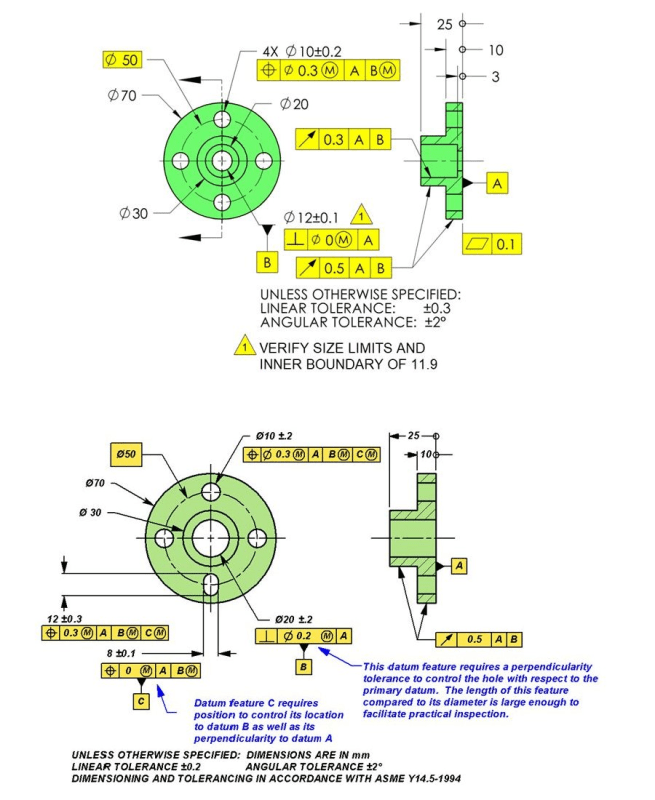
Can anybody have a though how to inspect tertiary datum feature position tolerances? I mean, part still can rotate around datum B on plane A. How I can obtain tolerance position of datum C? Bottom example

september-98-2_2_h7guds.png
 
Replies continue below

Recommended for you

The center plane that is limited to the extent of the feature needs to lie within those limits for a plane that is perpendicular to the plane [A] and passes through axis of . The part is turned about to discover if that is true or a gage feature that correspond to the virtual condition for the feature is used.

It would be more a more obvious example if that was a shallow slot that went all the way across the part so that the nominal center plane of the feature was located directly on the axis of . You would then see that the slot is acceptable if centered on the hole within the given tolerance.
 
Hi, DimaM:

The slot (dimension 8+/-0.1) is a feature of size. The position tolerance of this slot indicates how far off its derived medium plane (center plane of the slot) are allowed from axis of datum feature B which is perpendicular to datum feature A. Position of the slot has nothing to do with rotation of the part. At max. condition, the center plane must go through axis B exactly.

Best regards,

Alex
 
As my understanding process of inspection of the part shall be like this:
First we inspect diameter hole B, then we inspect perpendicularity of this datum feature to plan A (and if hole go to the MMC it gave as bonus tolerance on perpendicularity).
After that it time to inspect feature C, with is slot. It have general tolerance of +-0.1 and it gives us bonus tolerance on position.
My question was how I can inspect this position "0m/A/Bm" ?
 
If using a CMM or similar, you would do your initial alignment to the A plane, then set your x,y origin to the B cylinder. Then to report your true position it would be the distance in terms of x perpendicular to the midline of the slot. The maximum deviation in terms of x would be +/- half of your accumulated tolerance from the MMC modifiers.
 
Hi, DimaM:

You will need to use a CMM machine to inspect position of 8+/-0.1 slot. If you don't have a CMM, you can inspect it using hard gages.

Below are general proceedures on how to inspect it using CMM machine.

1. Place the part on a fixture to do an initial alignment;
2. Probe the center hole (dia. 20) to establish datum B which is perpendicular to datum A.
3. Probe the slot (8+/-0.1) to establish its center plane (derived medium plane) that goes through axis of datum B and perpendicular to datum A.
4. Your CMM machine will report max. slot width which should not be over 8.1mm.

Best regards,

Alex
 
Dima,
The inspection can be done using a physical measurement fixture and CMM:

1. The measurement fixture: A fixture that includes a flat surface to simulate datum plane A and a fixed-diameter pin attached to it to simulate datum axis B. The pin diameter is 19.6, based on the virtual condition of the hole relative to datum plane A, calculated as the maximum material condition of the pin minus the perpendicularity tolerance in this state.

2. "Translation" of the measurement fixture to a virtual reference system: The CMM will sample points from the fixture itself and calculate from them datum plane A and datum axis B.

3. The tolerance zone for the slot position: It will be defined in the CMM software according to the datums calculated from the fixture. The zone will be two parallel planes to limit the slot’s center plane, perpendicular to datum plane A and centered on datum axis B. The size of the tolerance zone is the sum of the specified value of zero and the bonus obtained according to the actual slot width, measured ahead.

4. Relating the actual part to the calculated datums and tolerance zone, and measurement: The part is mounted on the fixture and rotated around datum axis B (around the pin) until the slot’s center plane enters the theoretical tolerance zone optimally (the measured position value is minimized). If the slot is produced with too large an offset from the hole or with excessive non-perpendicularity to datum feature A, it will not fit into the tolerance zone and will be rejected.
 
Back
Top