Continue to Site

Eng-Tips is the largest engineering community on the Internet

Intelligent Work Forums for Engineering Professionals

  • Congratulations waross on being selected by the Eng-Tips community for having the most helpful posts in the forums last week. Way to Go!

General case of angularity 2

Status
Not open for further replies.

CheckerHater

Mechanical
Sep 22, 2009
2,877
US
In recent discussion thread1103-442213 we opened Costco-sized can of worms regarding use of orientation controls.

Here is the question I wanted to ask but had a feeling that it would hijack the thread, add confusion to the discussion and not get as much attention as (in my opinion) it deserves.

I would like to collect opinions of members of the community to the problem:
How would you approach the case of angularity applied to surface randomly oriented wrt your coordinate system / DRF as shown on the picture?
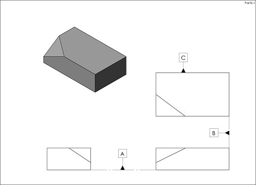
Part2_yi9d4x.jpg


"For every expert there is an equal and opposite expert"
Arthur C. Clarke Profiles of the future
 
Replies continue below

Recommended for you

Yes, a secondary reference can be used in the case of axis parallelism, just as long as everyone knows that parallelism to a secondary datum is not the same as parallelism to a primary. Parallelism to the secondary still has to be checked with the primary datum feature fully engaged with the simulator. The secondary will not likely be fully engaged to it's simulator. That's a point that a lot of people miss--in my experience, that is.

John Acosta, GDTP Senior Level
Manufacturing Engineering Tech
 
It actually occurs to me that as opposed to a planar feature axis perpendicularity will actually not benefit from a secondary datum reference. Axis vs planar perpendicularity and parallelism are reversed in this manner due to the symmetry of an axis versus a plane.

Edit spelling
 
CheckerHater,

Do all your outline features have to be perpendicular to the datum features? I had a design problem similar to this a few years ago, and I designed the part so that it could be orthognally fixtured between the datum features and the angled face.

I also provided section views cutting through the angled face parallel to the datum features. I intended this as an inspection resource.

--
JHG
 
drawoh,
Sorry, I cannot really visualize the problem in your question

"For every expert there is an equal and opposite expert"
Arthur C. Clarke Profiles of the future

 
CheckerHater

Where did the table come from in your earlier post?

Certified Sr. GD&T Professional
 
Belanger,
Sorry for the late answer. By my experience there are sometimes conpound angles where two angle controls at two separate sections is a beneficial practice.
Perhaps this case can be dealt with utilizing only one control, because the required section cut direction can easily be determined as ahown by CH in his figure with the single section cut.

CH, I don't agree that you can alter the datum precedence order. In your example involving angularity to |A|B| the tolerance zone would not change when you change the datum sequence only for an ideal part. For an as-produced imperfect part the datums and the tolerance zone will not be coincident between the 2 scenarios |A|B| versus |B|A|. Try to model an imperfect part and stabilize it according to each DRF, and define a tolerance zone basically oriented to the datums for each case. You will get two different tolerance zones.
 
Sem D220,
I agree with you that it is better not to swap datum precedence order.
I just hope you will agree with me that it is better to relate controlled feature to primary datum :)

mkcski,
ASME Y14.5.1M-1994(2004) Mathematical Definition of Dimensioning and Tolerancing Principles
(My faforite part of Y14.5 family)

"For every expert there is an equal and opposite expert"
Arthur C. Clarke Profiles of the future

 
CheckerHater: Thanks much. I do have a copy and it's my favorite too. I read it frequently to.............wait.......... fall asleep. hahahaah

Certified Sr. GD&T Professional
 
I have not been flowing this thread closely, but has anyone suggested profile to control the surface. To me, profile is more of a catch-all control (than orientation) and is "easier" to apply in unique situations like the compound angle surface. Just a thought.

Certified Sr. GD&T Professional
 
mkcski,
Yes, we did (sugested profile), but the OP (CH) said :"Let's not complicate it in that direction. We just want to check the angle"

greenimi said:
I suspect the surface is already located (profilled) to A, B and C, correct? Otherwise angularity only orients and never locates.

ch said:
@greenimi:
Let's not complicate it in that direction. We just want to check the angle
 
Small word in defense of chosen dimensioning scheme (as opposed to dimensioning parallel / perpendicular to datums):
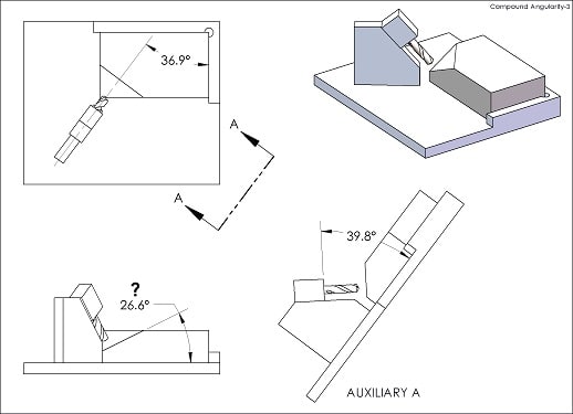
Let say, you want to make a fixture to drill a hole in said surface.
Suddenly, the numbers become very meaningful:
Compound_Angularity_kfsh6i.jpg


"For every expert there is an equal and opposite expert"
Arthur C. Clarke Profiles of the future
 
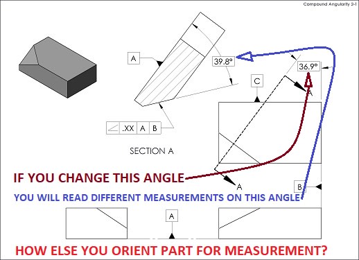
Regarding the second image posted by CheckerHater, "Compound Angularity 2-1":

The dimensioning scheme is perfectly acceptable, and it fully defines the basic orientation of the toleranced surface with respect to the datum features. The scheme suggested by chez311 is acceptable as well, although the same two angles could be equivalently dimensioned using edges in the views already shown. Various other dimensioning schemes would also be acceptable, including ones without any angular dimensions at all. Some of these schemes are certainly more useful than others for building drill jigs.

The angularity tolerance is perfectly valid as well, and the orientation of the tolerance zone is fully constrained with respect to the part. It would be equally valid for the tolerance to reference |A|C|, |B|A|, |B|C|, |C|A|, or |C|B|. If there is no need to fully constrain the orientation of the tolerance zone, then the tolerance could reference |A|, |B|, or |C|. The appropriate choice would depend on the desired result.

It doesn't appear that anyone here disagrees, but I figure it might be useful to write this down anyway.


Sem_D220,

In the scheme you proposed with two section views and two angularity tolerances, what exactly would the tolerances apply to? Also, what would the leader lines from the FCFs attach to in the drawing?


pylfrm
 
CH said:
I just hope you will agree with me that it is better to relate controlled feature to primary datum

You don't want to contaminate this thread. The most careful answer I can give to it now is that it is probably better to use only angularity or profile in many cases where 2 datums for orientation are needed, even where 0° or 90° relationships are controlled, and preserve a functional datum sequence:)

A question about your example - if you sample a line element along the angeled angled feature in a direction perpendicular to the direction of the section cut, is that line element nominally parallel to A? If not, perhaps 2 controls are beneficial over one in this case too.

pylfrm,
According to the scheme I proposed the tolerances would apply to the controlled surface (of compound angle), and call out 2 datums according to the part's functional interface. It would look similar to what CH showed, for each control.
 
Sem_D220 said:
According to the scheme I proposed the tolerances would apply to the controlled surface (of compound angle), and call out 2 datums according to the part's functional interface. It would look similar to what CH showed, for each control.

All right. Each tolerance would need to use a leader line terminated in a dot within the outline of the surface, and you would need to construct the section views such that the outline of the surface is actually shown.


Sem_D220 said:
if you sample a line element along the angeled angled feature in a direction perpendicular to the direction of the section cut, is that line element nominally parallel to A? If not, perhaps 2 controls are beneficial over one in this case too.

CheckerHater's section view cutting plane is perpendicular to datum feature A, so a line element perpendicular to the cutting plane would be parallel to datum feature A. Such a line element only exists because the cutting plane is perpendicular to the angled surface as well.

This seems like purely matter of drawing view layout though, so I don't see why it would make any particular tolerance scheme more or less beneficial.


pylfrm
 
As long as you can always orient the part for measurement to get repeatable angle measurements that represent the angle that should be measured in the drawing view you show, there is no problem with a single angularity control. If not, setting section cuts normal to datums B and C ( and A always), and conrolling the 2 angles that construct the compound angle separately, is a possibiloty possibility to consider.
 
Sem D220 said:
As long as you can always orient the part for measurement ... there is no problem with a single angularity control

Don't you think that to orient part for measurement you need second angularity control?

"For every expert there is an equal and opposite expert"
Arthur C. Clarke Profiles of the future

 
CH said:
Don't you think that to orient part for measurement you need second angularity control?

I think we might understand the word "orient" differently. According to my understanding: no. You don't need any (one or two) angularity controls in order to orient a part for measurement. You do need to orient a part for measurement in order to verify angularity controls, be it one control or two controls. I'm not nitpicking, I'm just not sure I understand your question, and answer according to my interpretation.
 
Compound_Angularity_2_t0zvf3.jpg


"For every expert there is an equal and opposite expert"
Arthur C. Clarke Profiles of the future
 
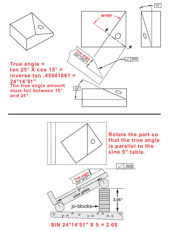
Compound_angle_measurement_y3gsmn.jpg


Snapshot from Measuring a compound angle by Gary Whitmire (Genium Publishing Co.)

Season
 
Status
Not open for further replies.

Part and Inventory Search

Sponsor