Continue to Site

Eng-Tips is the largest engineering community on the Internet

Intelligent Work Forums for Engineering Professionals

  • Congratulations waross on being selected by the Eng-Tips community for having the most helpful posts in the forums last week. Way to Go!

General case of angularity 2

Status
Not open for further replies.

CheckerHater

Mechanical
Sep 22, 2009
2,877
US
In recent discussion thread1103-442213 we opened Costco-sized can of worms regarding use of orientation controls.

Here is the question I wanted to ask but had a feeling that it would hijack the thread, add confusion to the discussion and not get as much attention as (in my opinion) it deserves.

I would like to collect opinions of members of the community to the problem:
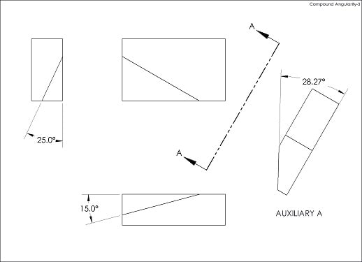
How would you approach the case of angularity applied to surface randomly oriented wrt your coordinate system / DRF as shown on the picture?
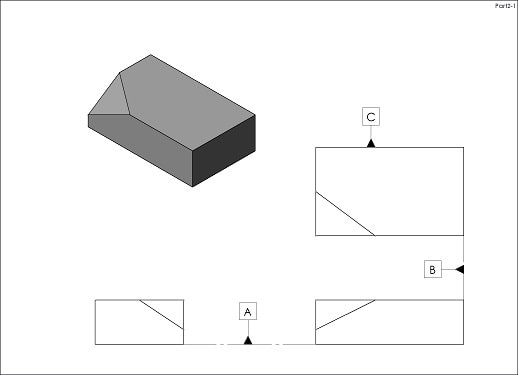
Part2_yi9d4x.jpg


"For every expert there is an equal and opposite expert"
Arthur C. Clarke Profiles of the future
 
Replies continue below

Recommended for you

pylfrm,
It would define the geometry, but it's a little less recommended. A section cut on the surface where an angle specified (which means a line element sample on the surface) or specification of an angle on the edge similar to how it's shown in SeasonLee's figure (which is nominally the same angle as in a section cut sampling any line element on the surface perpendicular to the relevant datum) is probably less problematic. The angle you suggest can only be measured on the sharp edge. If there is a fillet produced there on the actual part (for example if it's injected or molded), the angle will be hard to measure. If it's machined, deburring/edge break is small enough and the edge is adequately distinguishable, then the issues that were discussed in thread1103-439832 will be relevant.
 
It occurs to me that a more robust method is to take the cross product of unit vectors along the angled edges. The dot product of that result with a vertical vector [0 0 1k] can be used to get the slope angle and the [i j] components would give the true slope direction. This is advantageous when one of the edge angles is zero, avoiding a division by zero that trigonometric methods produce if one edge angle is 0. It also means that the faces don't have to be at right angles for the method to work.
 
Yes, the correct angle is 28.27 deg.

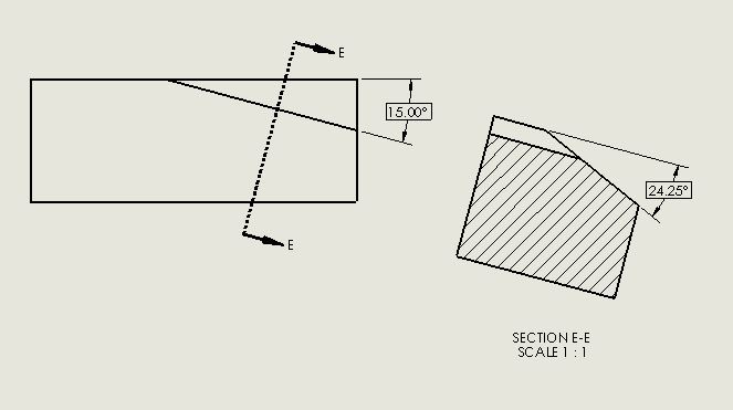
Compound_Angularity_usre4m.jpg


No, rotating part 25 deg and then 15 deg will not produce correct slope.

No, the formula provided by Gary Whitmire and copied by SeasonLee is not correct.

Unfortunately, there is very little overlap between generation that still remember how to correctly "flip" compound angle and GD&T crowd.

Sad.

"For every expert there is an equal and opposite expert"
Arthur C. Clarke Profiles of the future
 
CH said:
No, rotating part 25 deg and then 15 deg will not produce correct slope.

Then rotate it 24.25° and 15° and you'll be alright.
 
Sem_D220,

I'm glad you agree the 53.1° basic angle dimension would define the geometry. I'd say CheckerHater's proposed scheme effectively provides this dimension, by way of an implied 90° basic angle between the section view cutting plane and the edge. I'll gladly agree to disagree on this though.

Several times in this thread you've mentioned measuring angles. What exactly do you mean by this, and how does it relate to angularity tolerances?


pylfrm
 
pylfrm,
When I mentioned measurement of a true angle I meant a dial indicator measurement so that all the measured values should be nomibally zero mm or " when the part is oriented according to the specified angle.

I also mentioned measuring the basic 53.1° (per your dimensioning suggestion) angle, in that case the angle value to be measured in degree units. Theoretically with just angularity specified it shouldn't be done, but how else you would know the part is in spec? If you don't measure it, you would have to consider this exact angle when orienting the part for angularity inspection by rotating the part about an axis perpendicular to the face of the sine plate. If this is practical, then it's possible to skip the edge angle measurement. However if they just "rotate the part so that the true angle is parallel to the sin 5" table" (per SeasonLee's figure), 53.1° basic could be for example 45° on the actual part and the part will pass the inspection without meeting drawing specs.
 
Sem D220 said:
However if they just "rotate the part so that the true angle is parallel to the sin 5" table" (per SeasonLee's figure), 53.1° basic could be for example 45° on the actual part and the part will pass the inspection without meeting drawing specs.

I had just assumed this would be rotated through an exact basic angle, not just until parallel - otherwise it doesn't seem like a useful measurement for the reasons noted. Is this because its not practical to do so? I was taking Gary Whitmire's figure with a grain of salt as it was - for as shown the sine plate would have to be set to 28.27deg (the actual true angle) as noted by several other people, otherwise there is an error of 4.02deg.

That being said, also as suggested by semiond, the angle referenced (24.25deg) is still useful as it is taken perpendicular to the feature/surface of interest just in a different view than is shown in Whitemire's figure and can be utilized to measure the angularity tolerance. Could perhaps the angles below be utilized to create an acceptable dimensioning scheme? It may not be referencing the "true" angle/slope but it could be utilized to set up a compound sine plate similar to this one set at 15deg / 24.25deg.


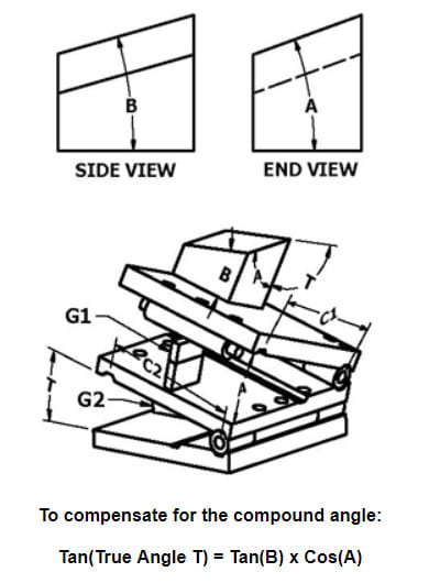
compound_angle_od9rkh.jpg
 
Something is wrong with that diagram - there are two angles marked "T" and they are obviously not equal to each other. It is also not the true slope with the bottom surface, but an intermediate angle. As shown it works to set up to make the cut, but Whitmire misunderstood what the true angle in that diagram meant.
 
This is how REAL formula(s) look like:

Capture_xytzhz.png


From this formula R = 29.88 deg ,C = 28.27 deg.

"For every expert there is an equal and opposite expert"
Arthur C. Clarke Profiles of the future
 
This diagram/equation is true - it looks like I made offsetting errors in my derivation so the true slope was the correct value, but the side the rotation is on is off by 90 deg - hence the sine vs cosine.


true_turn(t1;t2) = arctan(tan(t2)/tan(t1))
trueslope(t1;t2) = arctan(tan(t1)/(cos(arctan(tan(t2)/tan(t1)))))

are the corrected formulas for speedcrunch.
 
Looks like typical "Garbage In - Garbage Out" application.
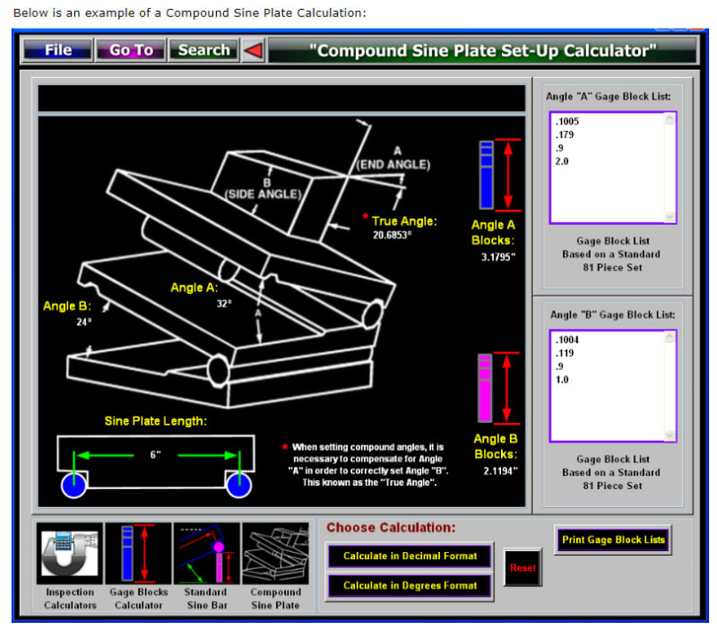
If actual angles on the part are 24 and 32 deg., then "True angle" will be larger then both of them, like 3DDave mentioned.
Actually 37.5 deg.

And, if you set your sine plates to 24 and 32 deg., your resulting orientation will be about 3.31 deg. off.

"For every expert there is an equal and opposite expert"
Arthur C. Clarke Profiles of the future

 
Actually it looks like its labeled incorrectly. Seems like this is a commonly misunderstood topic even when consulting the resources available.

If the angle A and B on the PART are 32deg and 24deg respectively then on the SINE PLATE angle A = 32deg and angle B = 20.6853deg which is what they have labeled as "true angle" and NOT the same as angle B on the part.
 
I suspect the compound sine plate makers/users have absconded with the definition of "true" and forced it to their own purposes. I'll just put it that the "true" angle value specified for the compound sine plate does not appear on any part drawing and is not applicable to any normal form of measurement, such as, but not limited to, an inclinometer.
 
For the part depicted in in Whitemire's figure including a 25°, 15° compound angle, I verified earlier by CAD that 24.25° (rounded a couple of micro-degrees) is the angle to set the orientation at, in addition to a 15° rotation, in order to have the slope oriented as a nominally horizontal plane (parallel to inspection table). That same angle results from using the tan(T)=tan(B) X cos(A) formula, mentioned in both Whitemire's figure and in the compound sine plate calculation (Thanks SeasonLee), while B=25°, A=15°. So actually the "true angle" is just one of the angles to set the orientation for measurement or machining, as also suggested by chez311.
The only question that remains is - what is the rule to determine which angle is A and which is B? If you switch them - you get a wrong result.
 
Status
Not open for further replies.

Part and Inventory Search

Sponsor