Continue to Site

Eng-Tips is the largest engineering community on the Internet

Intelligent Work Forums for Engineering Professionals

  • Congratulations waross on being selected by the Eng-Tips community for having the most helpful posts in the forums last week. Way to Go!

General case of angularity 2

Status
Not open for further replies.

CheckerHater

Mechanical
Sep 22, 2009
2,877
US
In recent discussion thread1103-442213 we opened Costco-sized can of worms regarding use of orientation controls.

Here is the question I wanted to ask but had a feeling that it would hijack the thread, add confusion to the discussion and not get as much attention as (in my opinion) it deserves.

I would like to collect opinions of members of the community to the problem:
How would you approach the case of angularity applied to surface randomly oriented wrt your coordinate system / DRF as shown on the picture?
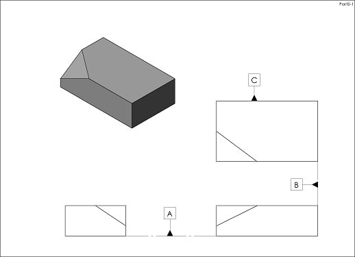
Part2_yi9d4x.jpg


"For every expert there is an equal and opposite expert"
Arthur C. Clarke Profiles of the future
 
Replies continue below

Recommended for you

CH, your diagram says that the angle of the section cut affects the measurement result for tye angle. It's true, but I still don't see how does that have to do with 2 angularity controls?
 
I guess we misunderstood each other, one FCF, but 2 angles, 2 datums and acceptable datum sequence.
Sorry. :-(

"For every expert there is an equal and opposite expert"
Arthur C. Clarke Profiles of the future

 
CH,
I think that the angle 36.9 in your sketch (which decides the section cut direction) shouldn't be basic. It can be reference or not specified at all. This is because this angle should be able to slightly alter per produced part, it will have to maintain right angle to the produced edge between the top surface and the slope. SeasonLees figure is very helpful too for understanding this.
 
Sem D220 and SeasonLee,
Just out of curiosity, how are you going to machine this surface?

"For every expert there is an equal and opposite expert"
Arthur C. Clarke Profiles of the future

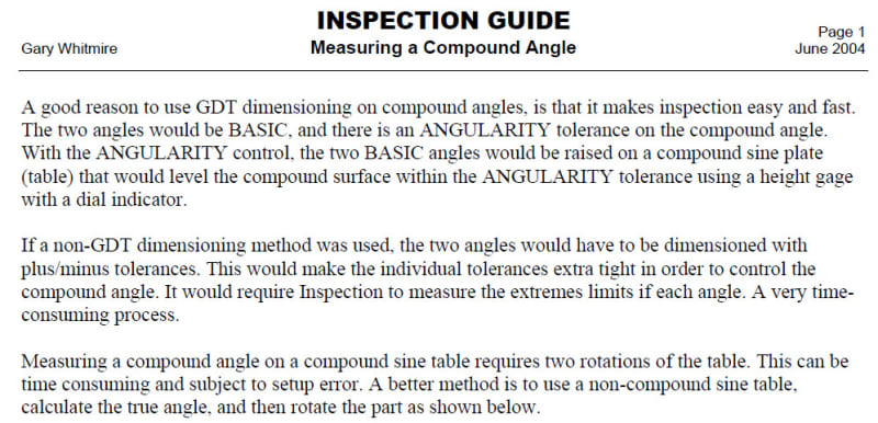
 
CH, If you mean the dimensioning scheme shown in SeasonLee's figure, one way is to orient the raw material block at the machine table similary to the way it is depicted on the sine plate and then mill that feature with horizontal tool feed. To orient the part correctly before machining you need to consider the two angles shown - 15°, 25°. I wonder why there are no datums specified at the angularity FCF, though.


But HOW you "consider" TWO angles with ONE sine plate?

"For every expert there is an equal and opposite expert"
Arthur C. Clarke Profiles of the future

 
If you're still asking about machining - you can utilize the rotary axes of the machine. You need 2 rotations. If it's a simple 3 axes machine you will probably need a fixture mounted on the machine table in which the part will sit oriented like it should 8n in 2 directions.

How to orient: consider the workpiece at the view where you see the 25° angle. Now give it one rotation of 25° counterclockwise, and then a rotation of 15° about an axis parallel to the bottom of surface of the part.

 
I leave it right here

"For every expert there is an equal and opposite expert"
Arthur C. Clarke Profiles of the future

 
CH said:
But HOW you "consider" TWO angles with ONE sine plate?

Just in case you were asking about the sine plate (measurement) - then you can simply follow the instructions in SeasonLee's figure :)
 
SeasonLee: Could you please post the ISBN number of the Gary Whitmire book you have been referring to?

Certified Sr. GD&T Professional
 
SeasonLee: Aahhhhh. I've seen this site and did not have the cash to buy the product(s) for my GDT library.

Certified Sr. GD&T Professional
 
FYI - you can register as a free/guest member and get access to a decent amount of the material. Some of it is still locked out and you obviously don't get their hardcopies/CD's, but its still a surprising amount.
 
CH,
I think that the angle 36.9 in your sketch (which decides the section cut direction) shouldn't be basic. It can be reference or not specified at all. This is because this angle should be able to slightly alter per produced part, it will have to maintain right angle to the produced edge between the top surface and the slope. SeasonLees figure is very helpful too for understanding this.

If the 36.9° dimension is removed, the basic orientation of the toleranced surface will still be fully defined with respect to datum feature A, but not B or C. It would no longer make sense for the angularity tolerance to reference datum feature B or C. Do you agree?


pylfrm
 
pylfrm, I agree, and I think that the substitute to that angle should be another angle defined on the angled feature itself. It could be another section cut perpendicular to either B or C (and A), depending on which one of them is functional and should be called out. As it is now, on the angled feature itself, only the true angle is defined, but not the "direction" of that angle. I don't consider specification of the direction of the section cut as a valid definition for the geometry because it only specifies the view, not part geometry. If it's fixed, it may force measurement of an angle that is not really the true angle.
 
season lee - the math is incorrect.

For side angles A & B the true slope will be greater than either of them. This can be deduced from inspection.

From the common vertex to the top surface is some distance Z. The distance along one face as projected to the bottom face is X and the distance along the other face as projected to the bottom face is Y.

The angle of the first edge to the bottom face is A = ATAN(Z/X). The angle of the second edge to the bottom face is B = ATAN(Z/Y).

Note that the ATAN function returns larger values for larger arguments. Note that the nearest point along the top intersection to the common vertex is closer than the common vertex is to the vertex along X and the vertex along Y - call the segment T, for the perpendicular segment from the common vertex to the top surface edge projected to the bottom face.

For non-zero A and B, T < X and T < Y, then ATAN(Z/T) > ATAN(Z/X) and > ATAN(Z/Y)

My calculation, given 15° and 25°, is a true slope of 28.2718085050179°

Added:

My previous solution was in GeoGebra which also shows the "rotate theta1; rotate theta2" method produces an error of 1.36° in the apparent slope when the claim was that the error would be 0°. However, the overlapping geometry is such that it's easier to have people recreate it on their own than spend time on explaining all the vertices and line segments, et al.

So I re-derived just the true slope calculation from trigonometry, where t1 and t2 are the acute angles along orthogonal sides:
turn angle from side with t1 = arctan(tan(t1)/tan(t2))
trueslope(t1;t2) = arctan(tan(t1)/(sin(arctan(tan(t1)/tan(t2))))))

It is notable that while the trueslope() function fails if t1 or t2 equals 0, for arbitrarily small values of either t1 or t2 the true slope approaches the value of the other; this was also a problem for the GeoGebra sketch - small values of t1 or t2 created geometry that is so large that it made the sketch unintelligible because the intersection approaches an infinite distance from the common vertex. So trueslope(0.0000001°,45°) will result in a value of 45.0..000x°, where an arbitrary number of zeros happens before the first non-zero digit. As demonstrated earlier, the true slope will be larger than either angle.
 
This discussion provides even more ammunition to all MBD supporters.
 
MBD is an entire other can of worms, worthy of it's own thread.
 
Sem_D220,

Would you consider a basic angle of 53.1° between datum feature B and the edge where the angled feature meets the surface parallel to datum feature A to be another acceptable substitute?


pylfrm
 
Status
Not open for further replies.

Part and Inventory Search

Sponsor