Eng-Tips is the largest engineering community on the Internet

Intelligent Work Forums for Engineering Professionals

Guardrail base connections 2

Status
Not open for further replies.

EngDM

Structural
Aug 10, 2021
367
1
16
CA
I see guardrail connections with 2 bolts/fasteners quite frequently, but I'm not sure exactly how to analyze these. I've tried putting it into Simpson's anchor designer but it can't find equilibrium. I'm sure these connections are okay since they are used often.

Where does the moment go when anchors are in a line? There is no T/C moment arm between the two.


Screenshot_2023-08-16_102954_c44ywp.png


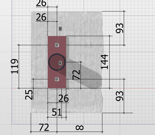
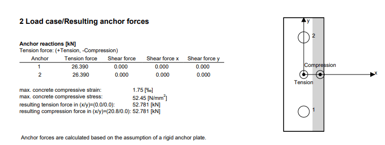
Profis seems to be able to model this and determine loads, however it still appears to fail since the compressive strength in the concrete under the compressive zone is exceeded. So how do these two bolt concrete connections ever work, since there is no way 55MPa concrete is specified for this.

Screenshot_2023-08-16_103655_idxnxi.png


I checked in DG1 but couldn't find anything with 2 anchors in a line perpendicular to the moment direction.
 
Replies continue below

Recommended for you

It's the same procedure used in DG1. Even when you have 4 bolts you don't assume two of them are in compression - there's no load path for that to happen. The DG1 procedure only uses two of the bolts, which is precisely what you have here. You just have a much smaller area for the compression reaction to form in. Hilti is using the DG1 rigid baseplate assumption there.

As for concrete bearing, how are you calculating it? Did you verify Hilti's answer? (I don't do metric so I have no idea how close that is to what I normally design.)

Just because "it's done all the time" doesn't mean it can actually be shown to meet code. A physical test might show that it works, but a lot of these details have just been around and, as such, aren't questioned by many.
 
Into steel, this can work out, since bolts are strong and steel is pretty tough (doubly so if you do some yield line checks). Into concrete I've never seen the numbers work. In fact, I've these break out of the concrete before when they were bumped by equipment. I use a four bolt pattern with a bigger base plate for my connections to concrete, or better yet use taller posts and side mount to steel below.
 
We require that the manufacturer of the guard submit the sealed calculations. They usually dust off a dog eared (if it was possible to have a dog-eared pdf) with an approach like above. I try not to look at it too closely, as it might give me bad dreams.
 
phamENG said:
As for concrete bearing, how are you calculating it? Did you verify Hilti's answer? (I don't do metric so I have no idea how close that is to what I normally design.)

I didn't double check Hilti's calcs, but the 55MPA is over double what standard 4000psi concrete is. I saw in another thread that Hilti doesn't check the concrete whatsoever, just the anchors. This calc is hidden in their design report and not actually displayed when sizing so it is often overlooked.

Is there any information in DG1 with circular columns as opposed to rectangular (other than yield lines being calculated at 0.8 x diam)?
 
I'd start by making the base plate wider. You don't even have enough to weld to.

What loads are you using - I see there is no shear force in the anchors.
 
I agree with the previous responders that I have never seen a two-anchor connection into concrete meet Code. Just because that's the way it was done, doesn't mean it works. You can run the numbers using DG1 (with large moments) and it will tell you that you need to use a much larger base plate to meet Eq. 3.4.4. We delegate the design of the post connections to the railing manufacturer, and we are seeing four-anchor connections on newer construction. Hopefully someone has finally got the message.

Don't forget you can reduce the impact of the 200 pound point because the load is distributed to adjacent posts through the top rail. You can run an FE analysis or refer to the Metal Stairs Manual for estimated reduction factors.
 
I look at this type of base to only resist moment in one direction. It needs to be part of a frame in the other direction as it can resist shear. But, I don't rely on it to resist moment.

That's certainly a personal preference. I could analyze it to resist SOME moment, but I don't think it will work for the type of base moment I'd typically see for a single guard rail post.
 
Assuming the post fits on the plate with room for weld + 1/8 added clearance... the force on the two anchors is the moment / 26mm. This is divided by 2 because of the two anchors. This force is resisted by the plate having a moment of (144mm - 0.9 x dia post)/2 - 25mm [adjusted for prying action]. The plastic section is used to calculate the resistance of the plate...

Design the anchors for the tension and their proximity...increase spacing and size as required.

I have SMath programs for the following bases:


Clipboard01_oacwrw.png


06Bc and 06Bs do it for circular and square tubes, respectively. The programs calculate for combined tension and shear, but the shear component is just a fraction of the tension force.

-----*****-----
So strange to see the singularity approaching while the entire planet is rapidly turning into a hellscape. -John Coates

-Dik
 
JLNJ said:
I'd start by making the base plate wider. You don't even have enough to weld to.

What loads are you using - I see there is no shear force in the anchors.

The posts in Simpson don't allow you to go smaller, that was just the smallest size.

I hadn't added a shear load as I was only trying to work out how they get the tension force from it.
 
The min width of plate, I use, is the dia of the post, 2 x the weld size + 1/8" to allow for 1/16" outside the weld. I also reduce the post to .9, like I do for columns and my program allows for ASTM A500 HSS reduced dimensions.

I include for shear, but since the shear load is just a small fraction (generally) of the tensile load it almost never comes into play. I also do a check for 10% overload just to draw my attention to the stress conditions.

-----*****-----
So strange to see the singularity approaching while the entire planet is rapidly turning into a hellscape. -John Coates

-Dik
 
Thanks pham... a BPS. I'll check and reduce even further. I can see that for circular, but I reduce for both circular and square/rectangular sections. In reality, it's almost a beam
section, and I used the 0.9 thinking it was behaving like a column-flexure in some fashion. Using 0.8 will increase the plate moment a tad (normally doesn't govern).


-----*****-----
So strange to see the singularity approaching while the entire planet is rapidly turning into a hellscape. -John Coates

-Dik
 
I'd expect that concrete to be stronger in compression than 52MPa. Afterall you'd expect it to be confined not unconfined unless it is near an edge. I'd expect the steel to bend, the anchors to fail, potentially if they are shallow anchors for you to have global failure of the concrete along a shear arc.

None of that is being checked.
 
I check for confined compression in concrete in my SMath programs as well as combined stresses, prying action and use of ASTM A500 HSS sections.

-----*****-----
So strange to see the singularity approaching while the entire planet is rapidly turning into a hellscape. -John Coates

-Dik
 
canwesteng said:
To beat factored bearing of 52 MPa, you'd be looking at 28 day of almost 50 MPa and full confinement
In the real world the loads aren't factored, they are what they are. And confined 32MPa concrete can take more that 32MPa.

I'm not saying that the calcs work out. I'm saying that in many cases it IS sufficient to remain in place.

Sorry if I was unclear. I'm in complete agreement with most of the comments above. I was just pointing out one on the factors why these things DO work most of the time.

 
It wasn't a rebuttal... What I don't do, and maybe I should is to reduce the fastener depth by 1/2 the compression block of the concrete... using a compression block based on the width of the base and the higher confined strength... I just have an array to accommodate if it's confined or not confined. I usually determine this by proximity to the edge.

-----*****-----
So strange to see the singularity approaching while the entire planet is rapidly turning into a hellscape. -John Coates

-Dik
 
Status
Not open for further replies.
Back
Top