Eng-Tips is the largest engineering community on the Internet

Intelligent Work Forums for Engineering Professionals

  • Congratulations waross on being selected by the Tek-Tips community for having the most helpful posts in the forums last week. Way to Go!

Hard Rock Hotel under construction in New Orleans collapses... 119

Status
Not open for further replies.
miningman said:
I cant help but wonder how many of these monday morning quarter back players, have ANY blasting experience whatsoever.

I have zero blasting experience.

Why would they only sever the support cables at the top of the crane and not the connections where the tower meets the boom and the tail?
 
My 'blasting' experience goes back to a very short time in the ARMY Corp of Engineers (Reserves). Never actually got to blow anything up, just some classroom work learning about stuff like C4 and other military-grade explosives.

Note that this was during the Vietnam era, and one of our instructors explained the two best reasons for being in the Corp of Engineers. First was that since we traveled with our own power generators, we always had cold beer. And second, we had C4, so we could 'dig' a foxhole in a minute or less, without working-up a sweat.

John R. Baker, P.E. (ret)
EX-Product 'Evangelist'
Irvine, CA
Siemens PLM:
UG/NX Museum:

The secret of life is not finding someone to live with
It's finding someone you can't live without
 
HorsieJuice said:
I have zero blasting experience.

Why would they only sever the support cables at the top of the crane and not the connections where the tower meets the boom and the tail?

Those are probably the most robust pieces of the crane? I'm guessing they would use some sort of shaped charge to do that. Between getting all of that placed on a tight time schedule and maybe some concerns about containing it all (i.e. not sending high velocity shrapnel a mile away), the cables were just easier.
 
They severed the cables at the top because they carried the weight to balance from one side to the other. By severing those cables the loads on both sides were simultaneously released. What they didn't seem to appreciate is that leverage brought the two significantly different weights into balance and without that cable the leverage was removed, leaving the unbalanced weights to act independently.
 
Spartan5 said:
Those are probably the most robust pieces of the crane? I'm guessing they would use some sort of shaped charge to do that. Between getting all of that placed on a tight time schedule and maybe some concerns about containing it all (i.e. not sending high velocity shrapnel a mile away), the cables were just easier.

If you're trying to drop the tower in a specific spot, I'd think the forces applied by the falling boom & tail would prove to be significant factors that you'd want to control. The attachment to the boom is what kept the one tower upright and the attachment to the tail is what appears to have started the other tower tumbling end over end as it fell.
 

I have said this exact thing to my colleagues. Couldn't imaging something like this happening with full occupancy - like Mardi Gras or the 2024 (?) Super Bowl.
 
Note 18 under Steel Notes on the permit drawings: "THE STEEL FRAME IS "NON-SELF SUPPORTING". ADEQUATE TEMPORARY SUPPORT MUST BE PROVIDED BY THE CONTRACTOR UNTIL REQUIRED CONNECTIONS OR ELEMENTS ARE IN PLACE."

That note is vague enough to cover a multitude of sins, but it is telling that some on the jobsite and photographic evidence, post-collapse, have indicated that in many cases only two bolts had been installed, even on floors that otherwise seem to have complete framing. Someone will have to look at photos and the building in its current shape to determine if the "connections or elements" were in place.
 
After looking over the plans (which I lost and can’t find now) if I may offer a few observations:

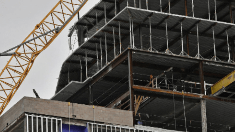
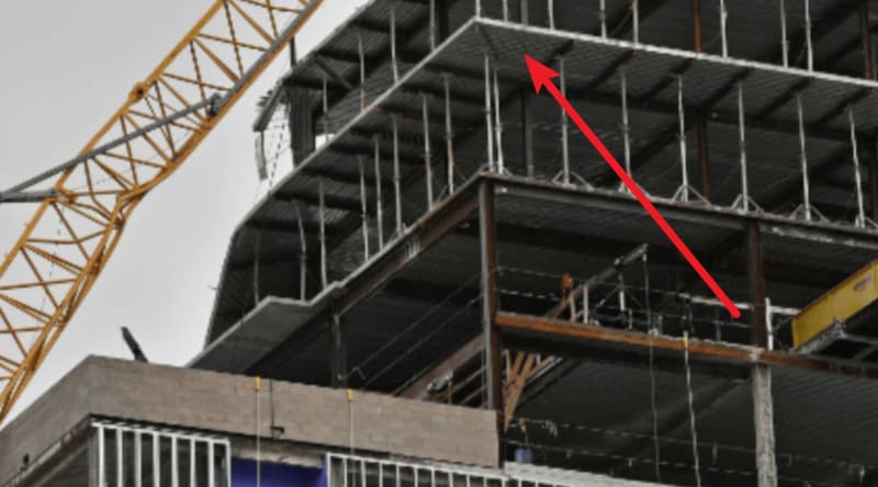
1. The tubes attached to the spandrel beams are structural as demonstrated by the orthogonal deck span that changed directions in the cantilever.

2. The beam supporting the cantilever would be in torsion unless it is tied back by the back span reinforcing.

3. I see no serious back span top steel steel the back span in close ups posted at the failure (such as with the man in the yellow suit)

4. I see that the cantilever steel is in the second layer of steel in the failure area if the steel exists.

5. The effective depth of the cantilever steel, if existent, is about only an inch or so in the failure area which further illustrates the structural nature of the HSS sections.

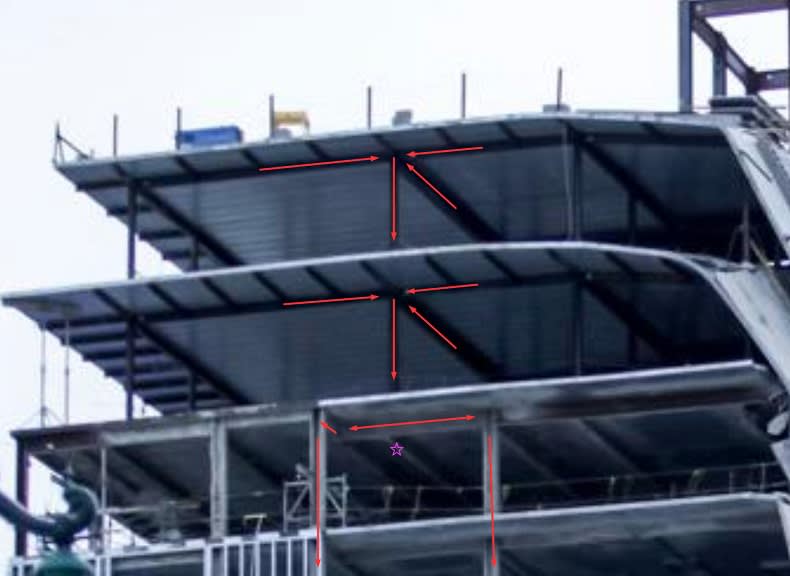
6. Since the outer slab cannot function as a cantilever, its load would be taken to the cantilever beams, then to the shores.

7. I propose that the shores may not have been removed after pouring each slab, therefore leaving the load in the shore rather than transferring it to HSS sections.

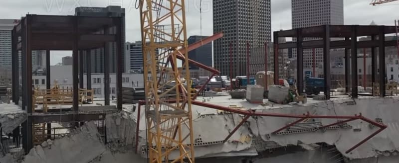
8. The shores finally buckled due to over-load of carrying multiple floors and the collapse proceeded.

9. Could it be that the HSS tubes were to connect to something else at their cantilever end to support them and "make it good" and were to be shored until that time?

Regards to all.
 
I was wondering the same thing and had looked for answers in the later (5-1-19) architectural drawing set. Some sections show a curtain wall below the cantilevered tubes, but I do not believe they would be designed as load bearing elements. There is a gap with backer rod and caulking shown between the top of the curtain walls and the structural framing above.

But who knows? Maybe the curtain walls were meant to be load bearing and that’s what the note about “non-self-supporting framing” and “required elements” was referring to.
 
The non self supporting frame note is common for steel frames. When we use a similar note, it refers generally to lateral stability. Erectors typically use temporary cables to brace the steel frame until lateral braces are installed, moment frame connections are complete, metal decks/concrete slabs are installed.

 
Screenshot_2019-10-24-15-16-39_bg8sbk.png


View of the underside of the (load transfer) 16th floor showing framing different than plans submitted with the permit, obviously they had been revised. It would be nice to get a copy of the latest revisions.


Double cantilever in the photo above is interesting. I don't see how it could possibly work at the slab and metal depths assumed. No beam to take the load. Was the bottom steel deck split at a 45 degree angle?

I could find no plans for reinforcing the metal deck with top and/or bottom steel.

I have the printed permit set now. It is obvious much is missing from them and many changes were made as discussed in this forum.

Regards,


It's hard to tell with the quality of the photo (at least, the quality as it shows up on the webpage, maybe the original is better), but it almost looks like the decking is at a 45 degree angle to the supports in that corner..? It may just be weird shadows.
 
Can you apply for a code exemption to the effects of torsion in North America?

That double cantilever looks mighty suspicious to me given the beams/girders appear to be I sections. I cannot comprehend how that even works unless the beams were simply there as permanent formwork to support the metal decking and the slab topping thickness did all the business cantilevering over the main beams. Either way it seems like the designer missed something fundamental if the framing that's visible was intended to be the final structure.
 
I think we’re largely guessing as to what’s going on with the apparantly unsupported cantilevers.

There are a lot of questions about this structure, as there are when any structure falls down. But we should probably stick to what we know for sure.
 
Interesting, GPR Tech's picture shows the cantilever holding up without shoring. I saw in some earlier pictures what appeared to be rebar in the slab. I wonder if the intention was for the concrete to act as a cantilever? I suppose if we ever get to see the final drawings we will know.

One thing I can't quite get my head around is even with the weak overhang and long span on interior decking is why there was so much of the building that collapsed? I can understand localized collapse but why the whole front part of the building? It seems like the steel frame would have the ductility and strength to have stopped a local collapse of the deck.

I personally find this one more interesting than the FIU bridge collapse. The design seemed to have some very obvious deficiencies in the plan set (long span's, questionable cantilevers) that many people experienced with construction would have noticed. It is also a fairly typical project without many (any?) technically challenging elements like the FIU bridge.

I wonder if this will get the same level of investigation and data disclosure that the FIU bridge has. The cause of this collapse is probably more relevant to many structural engineers daily practice than the FIU bridge.
 
Elevator Towers without diagonal bracing installed.
Has anyone seen any photos showing Elevator Tower's diagonal bracing installed on any other elevation?
Tower3_owfsbp.jpg

Elevators_dwg_ylrhvi.jpg
Elevators_cssaa9.jpg
 
Status
Not open for further replies.
Back
Top