Continue to Site

Eng-Tips is the largest engineering community on the Internet

Intelligent Work Forums for Engineering Professionals

  • Congratulations KootK on being selected by the Eng-Tips community for having the most helpful posts in the forums last week. Way to Go!

Hard Rock Hotel under construction in New Orleans collapses... 119

Status
Not open for further replies.
This is the quote from AISC that clearly explains the cause of Hard Rock hotel collapse.
"While ordinarily the existence of masonry walls provides enough lateral support for tier building frames to control lateral deflection, the increasing use of ... wide column spacing for high-rise structures not provided with a positive system of diagonal bracing can create a situation where only bending stiffness of the frame itself provides this support.
In this case the effective length factor, K, is dependent upon bending stiffness provided by the floor. If combined stiffness provided by the beams is sufficiently small, relative to that of unbraced column, effective length, Kl could exceed two or more story heights."
The picture of the building after collapse showing large sagging slender floors and inclined stiff columns clearly confirms that this is the case. The collapse had happened because of huge insufficiency of steel beams.

 
Boris,

Please provide a link to where you found AISC's statement.
 
Here is the FULL quote that Boris Kuznetsov has posted above (from AISC September 1986 LRFD Specification, section C2)
(bold emphasis mine)

AISC said:
While in some cases the existence of masonry walls provides enough lateral support for their building frames to control lateral deflection, the increasing use of light curtain wall construction and wide column spacing for high-rise structures not provided with a positive system of diagonal bracing can create a situation where only the bending stiffness of the frame itself provides this support. In this case the effective length factor K for an unbraced length of column L is dependent upon the amount of bending stiffness provided by the other inplane members entering the joint at each end of the unbraced segment. If the combined stiffness provided by the beams is sufficiently small, relative to that of the unbraced column segments, KL could exceed two or more story heights.

Note that this refers to the lack of external lateral bracing systems in a building - placing the lateral stability of the building on the frame system itself (beams and columns in a moment frame type assembly).

I don't think this is what the New Orleans building had - as it had external systems that braced the beams/columns that collapsed.


I think that the Designer made the same mistake as JAE in his post, he considered the whole frame as braced. The external columns located near the walls have X braces and can be considered as braced. However, the internal columns located in the middle of the building should be considered as unbraced because they do not have any braces and located too far from the walls. As a result of this mistake these columns got lateral movements impossible for braced columns and the building r collapsed.
 
Boris said:
However, the internal columns located in the middle of the building should be considered as unbraced because they do not have any braces and located too far from the walls
This is simply wrong. Each and every column doesn't need a "brace", they only need a floor diaphragm.

The overall building had three central cores of shear walls and diagonally braced "towers" across the building width.
These cores were only about 60 to 70 feet apart.
The building also had FLOOR DIAPHRAGMS spanning between the cores.
Any competent floor diaphragm will brace columns otherwise designed with k=1.0. This is very typical of most all designed buildings.

Assuming you do know about floor diaphragms, perhaps what you are suggesting then is the following "logic":
1. The majority of the gravity columns, between the braced towers, were connected to the floor diaphragms for lateral stability.
2. The floor diaphragms were comprised of 5 1/2" to 6 1/2" thick concrete on metal deck - (not sure of exact thickness)
3. Somehow, the diaphragm deformation, or failure, allowed the columns to lean laterally through deflection or failure of the diaphragm.
4. This lateral/horizontal deformation of the diaphragm was very large.
5. The diaphragm then probably failed, leaving the interior gravity columns without lateral support.

If that is you assertion, you are suggesting that the entire diaphragm failed such that its ability to laterally brace these gravity columns was eliminated.
I don't buy that at all, there was still significant amounts of floor remaining between the cores - only the front PORTION of the floor collapsed.

The use of an effective length method on columns, where a k > 1.0 occurs, is for columns that participate in the overall frame stability for lateral stiffness.
These columns did not participate in building lateral stability.

They were gravity columns. The text you cite above from AISC is about moment frames. You are applying it to BRACED columns braced by the diaphragm and the building cores.

If they leaned due to diaphragm deformation, or from core deflection, then they still would behave with K=1.0
The leaning of the columns, and the resulting secondary (PDelta) forces would of course have to be included in the overall building design...added force to the global lateral system.

But this is NOT a K = 2.0 type situation.

I would agree that if the diaphragm failed then a large group of columns would have collapsed.

Not because K > 1.0 but because the lateral load path was eliminated.

I think the collapse occurred because they prematurely removed temporary shores of a VERY long span composite floor deck such that the deck/slab sagged so much that it imparted large moments into the columns and they buckled, creating a domino collapse.

But this is also speculation.


This frame was designed as a braced with rigid floor diaphragms and factor K=1. However when "they prematurely removed temporarily shores of a VERY long span composite floor deck such that the deck/slab sagged so much ...", the big group of columns became unbraced with semi-rigid floor diaphragms and factor K>1. Here's the quote that proves this statement.
"Rigid diaphragms have infinite in-plane stiffness ..., whereas semi-rigid diaphragms simulate actual in-plane stiffness properties and behavior...
Semi-rigid diaphragms should be modeled when significant in-plane deformation does occur, or when required by code."

The premature removal temporarily shores had the following effects.
1) The columns not having braces and located far from walls became unbraced.
2)Bending moments and shear appeared in these columns.
3)Effective length and factor K increased in these columns and corresponding critical loads decreased.
Therefore the premature removal temporarily shores could lead to the building collapse with high probability.

 
Boris, I just have to stop after this post. Keep posting if you wish to.

You started out here blaming a swimming pool back last November.

Then you posted a formula that supposedly allows one to check if their concrete floor diaphragm is stiff enough.
Several people here asked for the source of that formula, which you never provided.
Typically in, say, several thousands of floors, built over the last couple of centuries, a 5 1/2" to 6 1/2" concrete floor is stiff enough.

In February you started talking about PDelta effects because the "bracing system was not rigid enough". None of the building's main bracing cores failed from what I understand.

Also in February, jhardy1 shoots down your formula as crazy and unrealistic, showing with numbers how it provided extreme numbers.
You never responded with any clarification of your formula with respect to jhardy1's calculations. Why not?

Others asked again for a reference to the formula you posted - no response from you. Why not?
Then you quote an AISC Commentary from 1986 dealing with moment frames, which doesn't apply to this project.

Just stop.
We get that you think that the floor sagging compromised the horizontal bracing effect of columns and thus the "designer made a mistake" and should have used K>1.0.
But a vertical collapse of a floor from shoring removal really doesn't mean the cause of the collapse is a designer using the wrong K value in design. It means the floor collapse and things fell down.
Your "source" cause of collapse (K > 1) is really an effect of something else.


JAE-
I once told my boy not to pee on an electric fence.

He did.

Sorry to say that I think you are wasting your time.

Brad Waybright

It's all okay as long as it's okay.
 
On the contrary, Brad. If the only thing required for the triumph of evil is for good men to do nothing, then it follows that the only thing required for the triumph of ignorance and misinformation is for the intelligent to remain silent.

JAE is speaking well reasoned engineering truth to (apparent) ignorance. Hopefully it will help Boris to reconsider his position and learn something. At the very least, it should help limit the spread of the misunderstanding.
 
I think any assigning of blame or root cause of the collapse is pure speculation at this point. To my knowledge, we don't have access to documents showing the current design. The only drawings that I have seen are the permit drawings with absurd member sizes and details.

If the building were being constructed in accordance to permit drawings, then the root cause will be easy to identify. I think we are about 6 weeks from the release of preliminary findings from OSHA and ASCE. Until we get document dump that hopefully will be a part of that, anything that we say on this forum is speculation.

If someone has access to publicly available documents that I don't, please provide us a link. At that point we may be able to have a productive conversation about the project and collapse.

Boris, you repeatedly site items as evidence of the cause of the collapse. YOU HAVE NO EVIDENCE! It is a misuse of the term and is wrong. You have speculation and that's it. I assume that ASCE is in the process of analyzing the structure based upon actual, in use member sizes. Once they release that information, I am all for a robust discussion on the merits. Until then, you just don't have enough information to continue this conversation. Boris, stop making statements as if they are fact.

I think the forum has been relatively silent, because we don't have anything new to discuss from an engineering standpoint. We get media reports and schedule updates, but nothing to add to the engineering insight.
 
Greetings.
The comment was just made, as had been made earlier, that some of the member sizes were woefully inaccurate or under designed, and it was suggested earlier that a practice in the computer analysis process was to select "place holder" members, with the purpose to create a stable framing configuration. That seems like something the software people could easily address - a specific designator as a "place holder" with a means provided that any print made or file created with an outstanding "place holder" must have the big red note saying the design is not complete and must not be used for construction and all such members so designated shall be clearly designated as such on the print or file.
Why you would input a small member with small properties without any reasonable size estimate is beyond me. I like the previous comment that if doing so, use something so big that everyone will call you with a question.
Thanks,
 
Vance, I don't think it was the analysis but rather the BIM model that had the "placeholder" (if, indeed, that is what happened).

I have to disagree with your idea. How annoying would it be if, every time you (or your draftsman/modeler) went to enter a member it gave you a prompt: "Did you actually design this member or is it just a placeholder?" I think it boils down to the Engineer in Responsible Charge being responsible for his/her design and the associated documents. If it doesn't have a design that you're confident can be built and loaded safely, make sure it's labeled correctly and NOT FOR CONSTRUCTION.

Of course, I have no idea if this was or wasn't a contributing cause - as OHIOMatt just mentioned, there's still a lot we don't know.
 
Vance/phamENG

We were talking about this internally from a Revit perspective a few months back. When you load a new beam size in that wasn't in the project at that point, for whatever reason, Revit defaults to the smallest beam in the beam family. So if you have 30 beams highlighted and you load the new member type in, it will make those 30 beams the smallest in the family, unless you catch it at select the desired beam size. If these beams aren't tagged yet, it presents and even larger opportunity for it to be missed somewhere down the road.

Ultimately, I agree with you phamENG that it is the EOR's responsibility to make sure it is correct. I am the EOR on almost all of my projects and rarely have drafting help. Being new to Revit, the above issue has caught me a few times, enough to the point that I am incredibly cognizant when loading beam types in.
 
BadgerPE - Thank you. I was unaware of that. I've never had to do much in Revit - trained in CAD but had dedicated modelers to run BIM/Revit. I know how to look around, change a beam size, and do basic things. One day soon I'll be forced to learn it in a lot more detail.

Given that perspective, I'll walk back some of what I said (though not the part about responsibility). I agree with Vance, then, in that if the program is going to automatically change a beam size, it should drive it to the largest in the family rather than the smallest.
 
Regarding the 'automatic' beam sizing.

I don't know revit at all, but with solidworks I can define a structural shape for a weldment or structure system part and I can also define the section name as it will show on the automatically generated cut list. Maybe in revit a user or administrator could define a section as 'unassigned' or 'placeholder' or something similar. This way unnassigned steel sections would stick right out on a cut list used for design review. Lots of times 'try harder' is a management solution to quality/safety problems when removing banana peels to before people slip on them is better.
 
Vance said:
Why you would input a small member with small properties without any reasonable size estimate is beyond me. I like the previous comment that if doing so, use something so big that everyone will call you with a question.

Yes it doesn't make much sense to populate with small members (or first guess members), but it's pretty common. We do it. I don't like it at all. I agree a designed/not-designed flag attached to each member is good idea. Using huge members is a bit of a kludge but certainly better than using small members which can slip through.

Judging from some of the member sizes we see on peer review projects it appears to be a somewhat common problem.
 
The demo company, DH Griffin Wrecking, was unable to get the 50 million in insurance that they wanted, so the owner wants to demo the building in a traditional manner. The city want it done fast, but now the COVID-19 disaster is making the Hard Rock collapse look like small potatoes.

 
Until there is a report on the exact nature of the structure and the defects it's irresponsible to give any conclusions about how the collapse happened. While there is a lot of speculation here, it is tempered by the lack of any reliable documentation about what exactly was built. That's the reason for the delay.

If you would like to treat the subject of such failures in general, I recommend "Engineers of Dreams" by Henry Petroski who wrote it specifically for that purpose. It targets bridge failures, but still covers the gamut of structural problems. This will form an excellent basis to understand any structural reports that are published. I expect it will be a very long time before the motivations of the participants in this disaster are finally explained.

So far OSHA has released a Citation and Notice of Penalty which contain some hints; I see no formal report analyzing the failure from them.

I tried to find this on the OSHA site; this is a link that a news agency posted:

from


Of course it is scanned and not searchable.

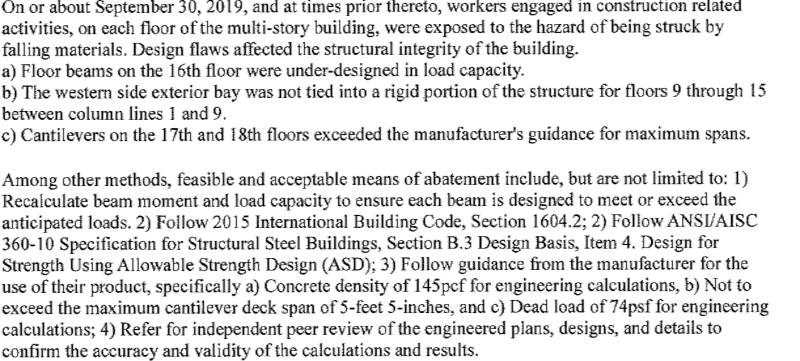
An extraction by Nola.com:
An image of the scanned-to-PDF OSHA Citation against Heaslip Engineering, LLC:

hard_rock_osha_clip_fls9so.png
 
Status
Not open for further replies.

Part and Inventory Search

Sponsor