Eng-Tips is the largest engineering community on the Internet

Intelligent Work Forums for Engineering Professionals

  • Congratulations waross on being selected by the Eng-Tips community for having the most helpful posts in the forums last week. Way to Go!

Headed Studs in Tension 7

Status
Not open for further replies.

dik

Structural
Apr 13, 2001
25,568
CA
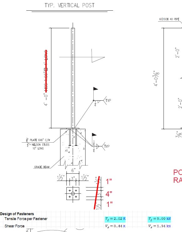
I have a project that has a couple of headed studs on a baseplate for a guard attachment. They are in proximity to eachother (4"). Does anyone have a spreadsheet that can be used to determine the tensile capacity. Or point me to something I can quickly use. Alternatively if someone can point me to a paper that addresses this. I've done an internet search and am saturated with the amount on non-useful information.

thanks Dik

-----*****-----
So strange to see the singularity approaching while the entire planet is rapidly turning into a hellscape. -John Coates

-Dik
 
Replies continue below

Recommended for you

I think that Hilti Profis handles this condition.
 
Thanks Koot... I'll take a gander.

-----*****-----
So strange to see the singularity approaching while the entire planet is rapidly turning into a hellscape. -John Coates

-Dik
 
Thanks jay... I tried signing into Hilti Profis, and they want be to re-log in. I find it a nuisance when they make improvements. Just got a recent update for Adobe Reader that was an 'improvement'... it basically rendered the editing 'totally useless'. I rely on being able to mark up *.pdf shop drawings for sealing...

-----*****-----
So strange to see the singularity approaching while the entire planet is rapidly turning into a hellscape. -John Coates

-Dik
 
I see two options for determining the tensile capacity of the headed studs, one from the steel code and one from the concrete code:
[ol 1]
[li]AISC 360-16, Section I8.3b, (p. 16.1-109): Tensile Strength of Steel Headed Stud Anchors in Composite Components[/li]
[li]ACI 318-14, Section 17.5.1.2(a) (p. 247): For cast-in headed stud anchor[/li]
[/ol]

I believe that using either code will result in the same capacity in this case.
 
Thanks...

-----*****-----
So strange to see the singularity approaching while the entire planet is rapidly turning into a hellscape. -John Coates

-Dik
 
I'm assuming that you're asking about the tensile strength of the steel studs and not the overall capacity of the entire assembly pulling out of the concrete. Just wanted to clarify.
 
I'll be designing them for pull out from concrete...

-----*****-----
So strange to see the singularity approaching while the entire planet is rapidly turning into a hellscape. -John Coates

-Dik
 
dik said:
I'll be designing them for pull out from concrete...

Ok, then what I stated above is an incomplete answer. I recently spent a lot of time writing a piece of software for concrete anchorage design. As you're probably aware, the basic requirements are spelled out in ACI 318, Chapter 17 (which I found parts of to be borderline incomprehensible).

The reference PCA - "Notes on ACI 318-11" has some decent design examples in Chapter 34 which helped me a lot. In particular, for your problem, I think Example 34.2 (p. 34-38) will be helpful. It's for a group of headed studs in tension.

Chapter 34 also contains several tables with design capacities for single anchors in tension and shear.

I found Hilti Profis software as well as the similar program by Simpson Strong-Tie to be very useful as well. My opinion is that the complexity of the ACI code has made it nearly impossible to do this stuff by hand for anything but the simplest cases.
 
Do you have a dimensioned diagram of the stud joint and the loads being applied?
 
It's just conceptional at this point. Just adding prelim comments to what client wants... The guards are 4' high and spacing is at 5' with 1' cantilever... Posts need to be 1.90dia x 0.14 wall... The 10" embed is overkill, and eventually I'll need to confirm the design...and the base plate has to be 1/2".

Clipboard01_xqya6d.jpg


-----*****-----
So strange to see the singularity approaching while the entire planet is rapidly turning into a hellscape. -John Coates

-Dik
 
It was interesting to see your problem. Not being in your industry, I don’t know what you have to design to, but looking at the parts, assembly, loading configuration, etc can inspire ideas. The first, being what you are after, is the moment and shear generated at the plate interface. The moment resulting in tensile prying loads. Problem is defining the point of rotation. Is it at the centre of the post, thereby generating equal magnitudes of +ve and -ve stud axial loads, or do you take the rotation point at the plate edge, generating all but differing tensile loads. Next, what is being used between the posts and how is it fixed to the posts? If the applied load is applied between two posts, can the load, when reacted at the posts, cause the posts to rotate, causing additional shear to be applied to the studs? Just brainstorming, generating food for thought.
 
Just another point. Again, if the load is between posts, will the flexing of the part between the posts tend to pull the two posts either side towards each other? As the base plate rotates, putting the studs into tension by applying contact bearing load to the underside of the stud head, the contact load centroid will be offset to the stud shaft. Do you need to consider the resultant bending?
 
No... there is 200' of 'catenary posts' on the other side, with the tensile rigidity of the 'rails' being far greater then flexural rigidity... I really don't know how this works... it's really quite complicated, so I just look at a small part of it. I tend not to overthink guards...I might do 20 different guards in a week... with various bases...

Clipboard01_s2rrea.jpg


-----*****-----
So strange to see the singularity approaching while the entire planet is rapidly turning into a hellscape. -John Coates

-Dik
 
I have an SMath program similar... I'll compare it. It's not the load distribution but the capacity of the headed studs. The client's proposal was to have 10" embedment for 1/2" studs and my quick calc indicated half that was more than adequate. I decided to do up an program.

-----*****-----
So strange to see the singularity approaching while the entire planet is rapidly turning into a hellscape. -John Coates

-Dik
 
Based on a quick analysis using the information that you provided above, I agree that half of the 10" embedment should be more than adequate. My calcs actually show 2.5" embedment being acceptable, although I wouldn't go that low.
 
Thanks...

-----*****-----
So strange to see the singularity approaching while the entire planet is rapidly turning into a hellscape. -John Coates

-Dik
 
Grab a copy of the Canadian Precast Concrete Institute Manual. It has a whole section about headed studs, I think. Plus it's free!


If you need it, you can increase your breakout capacity of your tension anchor by using the compression strut to restrain it. There have been studies on it and there's a capacity increase factor you can apply based on it. If you need that extra bump I can look for it.
 
Status
Not open for further replies.

Part and Inventory Search

Sponsor

Back
Top