Continue to Site

Eng-Tips is the largest engineering community on the Internet

Intelligent Work Forums for Engineering Professionals

  • Congratulations pierreick on being selected by the Eng-Tips community for having the most helpful posts in the forums last week. Way to Go!

Help With Bending Stress Calculation 5

Status
Not open for further replies.

MarkJ_

Mechanical
Jul 8, 2021
9
Hello,
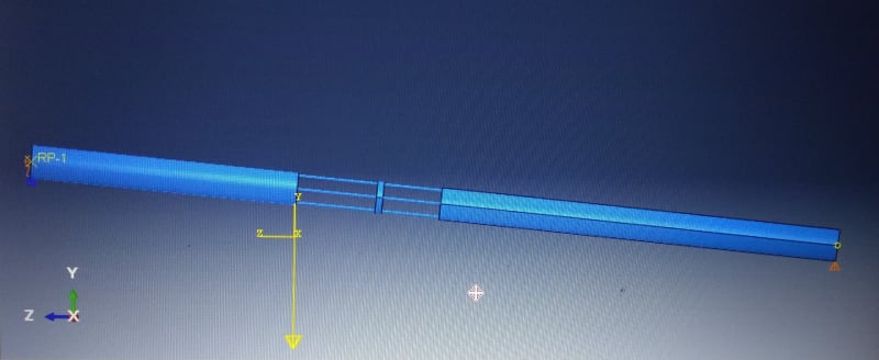
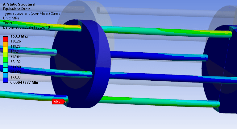
I was hoping to get some advice on how to calculate the strength of a new lifting interface. I have 2 existing tools that need to be joined together rigidly for lifting offshore. There are hydraulic lines between the 2 assemblies and access is also needed at the lifting interface for making these up. For this reason and because of space constraints I am looking to use 4 x 16mm OD threaded rods with a support plate in between.

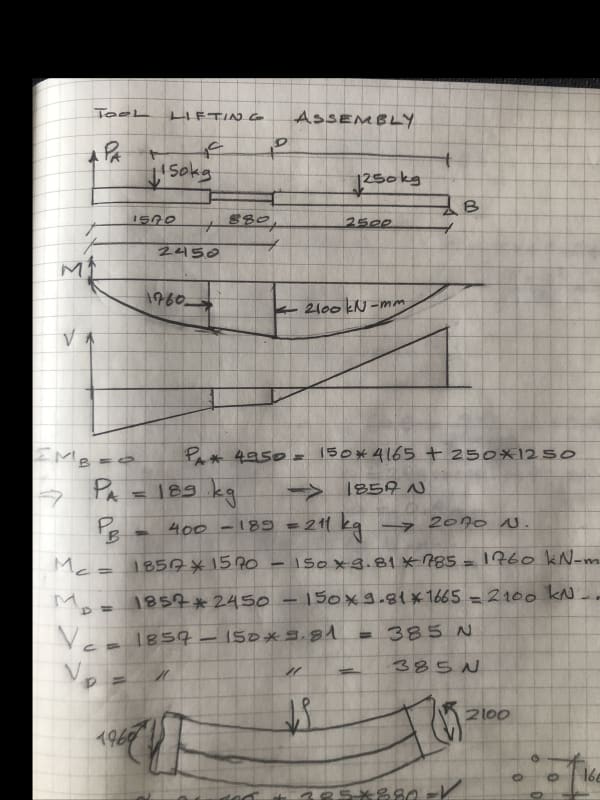
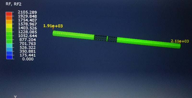
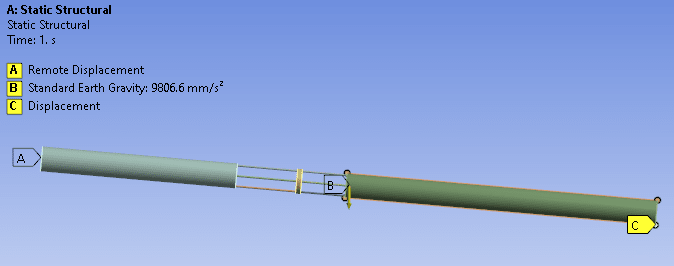
The top assembly with a single lifting point on its end face is rigid and weighs 150Kg. The bottom assembly is also rigid and weighs 250Kg. I have attached a sketch which shows the arrangement. The support plate and lower support rods (359mm long) are already existing which is why the support plate isn’t in the middle.

So the complete assembly will be lifted from horizontal to vertical using the single lifting point on the top assembly.

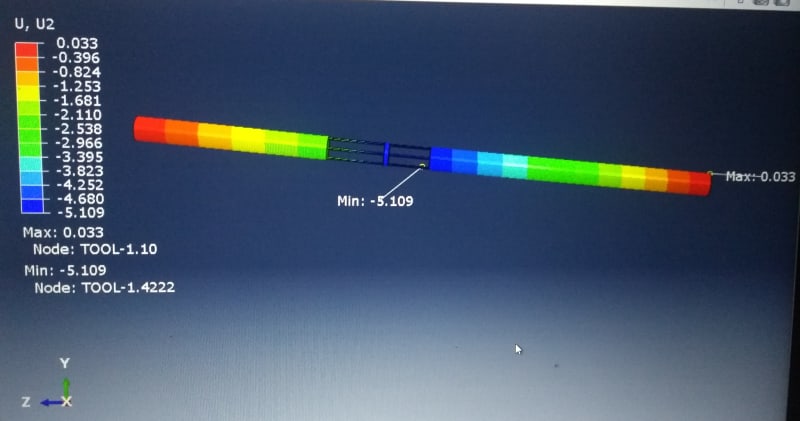
I was hoping someone could offer some advice on how best to calculate the bending stresses in the rods?

I tried doing this as a simply supported beam assuming the supports are where the rods attach to the top and bottom assemblies. I took second moment of area as being the formula for solid bar and calculated the bending moment halfway between the support rods and support plate. The stresses are very high and I’m pretty sure my calculation is incorrect.

Calculations are not my strong point. I would appreciate any advice?
Thanks
Mark
 
 https://files.engineering.com/getfile.aspx?folder=ee499a3c-12d7-42ed-9591-51af0658f0aa&file=Tool_Lifting_Sketch.pdf
Replies continue below

Recommended for you

HTURKAK said:
- If the rods are not connected to each other ( to get combined behavior , at least with diagonal elements like truss) , you can not assume the rods will behave as combined and you can not calculate the combined moment of inertia ..
- In this case the four rods will resist as separate elements

Then I am wondering how plate is connected and How the plate transfers the forces to the rods?
HTURKAK said:
- In order to assume group reaction is valid, the rods SHALL BE connected with web elements . The beam theory ( plain sections will remain plain after deformation ) is valid for composite elements when they connected to each other to transfer shear..

Is the plate not playing role of connecting member of all rods? I considered that rigid plate(compared to rod stiffness of course) connected to 4 rods and moment applied to rigid plate about horizontal central axis. I am wondering whether this assumption is totally wrong.

If I use F=M/d as rb1957 said and then for stress in rod F/A applies. So M=9199578.38Nmm for 0deg and D=166mm, F=55420N and then A=201.0619mm^2 gives stress in rod=275MPa which is again different approach than you. But still plate plays role of transferring the moment as "couple" of forces. I do not see why plate plays no role in either of situation.
 
"assumed pivot" (at the RH end) is an assumption ... the lifting point moves laterally (not saying it can't, up you'd think the lift would be up and the beam RH end would slide laterally to under the lift.

can you make a free body out of your diagram (first post) ? I can't see a moment restraint balancing the offset moment between the lift and the weight ??
Would the lift cause a up reaction (the end of the beam would push against the ground), so that the lift force is a portion of the weight (I'd thought it would be all the weight),
and now the weights are reacted by the lift and the RH end reaction. As I write this it sounds so obvious !!? (probably I confused myself thinking the lift = the weight)
then no lateral couple ... (sigh)

I would've assumed that the "kgs" were "kgf" (force not mass)

another day in paradise, or is paradise one day closer ?
 

DEAR NPR99,

- THE PLATE DOES NOT TRANSFER ANY FORCE..THE ASSUMPTION ,' THE RIGID PLATE DISTRIBUTES THE BM TO THE FOUR RODS ' IS NOT CORRECT AS LONG AS SHEAR EXISTS..

- IN ORDER TO ASSUME THE FOUR RODS BEHAVIOR WILL BE COMBINED BEHAVIOR AND THE MOMENT OF INERTIA WOULD BE THE INERTIA OF THE ASSEMBLY ( AS PER UR CALCULATION ), THE BEAM ASSEMBLY SHALL SUBJECT TO PURE BENDING AND THE INDIVIDUAL BEAMS ( IN THIS CASE FOUR RODS ) SHALL BE RIGID CONNECTED , AND THE SECTION AT THE TOP AND BOTTOM ASSEMBLY CONNECTIONS SHALL ROTATE RIGID..

IN ORDER TO CLARIFY AND JUST FOR SHARING THE KNOWLEDGE , I COPY AND PASTED A RELEVANT WORKED EXAMPLE FROM THE BOOK (Advanced Stress and Stability Analysis BY V. I. Feodosiev )

Beam_mit_pure_bending_qcnqii.jpg


beam_with_pure_bending_2_qrqbff.jpg


Beam_with_pure_bending_3_reply_trzids.jpg


Balken_mit_nur_biegemoment_4_jew7bp.jpg


I HOPE THIS RESPOND ANSWERS YOUR QUESTIONS AND DOUBTS..

GOOD LUCK..
 
Hi rb1957

Agreed that the pivot at the right hand end is a big assumption because like you say the whole assembly will at some point will slide which is part of the reason I only considered a 10 degree rotation. Now from my calcs above if I assume a couple as you suggest then the moment is 2100000Nmm which I then divide by the 117.63 dimension which yields 17890.6N, if I divide this by two and then find the rod stress using the rod area I get 44.5 N/mm^2 which is pretty close to what I got originally assuming the rods act collectively (50.3N/mm^2). Now another question if we rotate the rod arrangement by ninety degrees so that it looks like the diagram that NRP99 posted then we have two rods on the neutral axis and two rods at extremity of the beam ie
top and bottom so how would you share the couple now?. If I check the stresses in the rods at top and bottom of the beam with this arrangement it is 1.3 times greater than the 50.3N/mm^2 I got previously. If I have misunderstood what you are saying it might be worth you posting your calculations so I might understand better 👍

“Do not worry about your problems with mathematics, I assure you mine are far greater.” Albert Einstein
 
Thanks again for the amazing support you have given on this. It’s been incredibly helpful and educational. And thanks for providing such detailed calculations that even I can just about follow.

@Desertfox… one thing I can’t follow is how you have calculated the bending moments per your diagram? I’ve been staring at it and playing with my calculator for half an hour but can’t figure out how 2100 Nmm x 10^3 has been reached. Please can you clarify?

Thanks Again
Mark
 
Hi Mark

I took moments at the point loads, so to find the bending moment at the point where the 250kg acts,I took moments to the left of that point so :- F * cos10 * (785+2919) - 150*9.81 * cos 10 * 2919 = bending moment where the 250kg acts. Similarly to find the bending moment where the 150kg acts I take moments to the left of that position so : F * cos 10 * 785 and that’s how I got the original two values, the bending moment diagram between the two points is a straight line and so I drew a bending moment diagram to scale and measured the value from the diagram. Hope this helps

“Do not worry about your problems with mathematics, I assure you mine are far greater.” Albert Einstein
 
Mark, what sort of experience do you have ? The calc was well laid out (unless you're saying df dropped a clanger).

The clac shows that the RH end in supplying the rest of the weight reaction ..
loads weight is (150+250)*9.81 = 4000 N (I think we get here, to forces in N, whether the bodies mass or weight is given in kg)
Lift is 1857 N, so RH reaction is 2143 N

another day in paradise, or is paradise one day closer ?
 
Hi Mark

Having read through HTURKAK's last post I believe the rods will only act as individual beams and not act together as I originally thought, in which case I think the lift is doomed in its present state.

“Do not worry about your problems with mathematics, I assure you mine are far greater.” Albert Einstein


Eventually i am glad to be understood and a pink star for this respond..[pipe]
 
doomed is a pretty big word !

for 10deg, df calculates BM = 2.1E6, but HTURKAK calcs 9E6 ? (Nmm)

At zero deg, (max BM) the lift is approx 2000 N (the RH end reaction about 2500 N)
the moment is approx 2000*2500-1500*1300 = 5E6-2E6 = 3E6 Nmm (close to df's)
if the spacing of the active pair of fasteners is 166mm, then the couple is 18E3 N
if the bolt is 16mm dia, then stress is 18E3/200mm2 = 90 MPa (which looks low, but then I don't work in metric)

18kN is about 4000 lbs (2 tons) ... but a 1/4" (aerospace) bolt has an allowable of 4600 lbs, so 16mm is ok ??

another day in paradise, or is paradise one day closer ?
 
Hi rb1957

I think even using the moment couple it assumes that the rods work as one unit.

“Do not worry about your problems with mathematics, I assure you mine are far greater.” Albert Einstein
 
HTURKAK

I still feel that my assumption not totally wrong if not completely accurate. The behavior of rods will be in between the theoretical attached rigid plate and no plate like the combination of figure 237 and figure 36 of your post.
This is not just thought. I actually ran a simulation today (thought was not getting out of my head as a hard core analyst). I modelled Tool as single solid part considering rods "firmly" connected to the plate and both bodies. Adjusted mass of both bodies as given in the sketch by OP. Overall mass = 0.415tonne due to weight of plate and rods. Then fixed the lift point and only vertical point constraint of 5deg rotated tool at the other end where it just touches the ground. Applied only gravity load with elastic properties.

The von Mises stress at the bottom rod (my previous post image of plate with rods) at 2054mm from LH is 106MPa peak and 90MPa peak at 2453mm from LH. So what is assumed by me and rb1957 that the plate plays role in the transferring the forces is correct. Further this proves what rb1957 is saying that physically the plate will impart axial forces on the rods as couple. But there is something more to it.

From LH total mass supported = 4071.2N, then vertical reactions at close to 0deg, RL=2035.58N RH=2035.58N. Then 2035.58*2054-(150*9.81*(2054-1570/2))=2.314E6Nmm. Then M/d=2.314E6/166=13.938kN. Then the axial stress in the rod = 13.938kN/201.06mm^2=69.33MPa which is not close to 106MPa? rb1957 already shown the calculation for 90MPa at 2453 from LH.

But there are other things in the results. The rods at neutral axis not playing any role much but the stress is not entirely zero, either. As opposed to theoretical consideration of 90deg and 270deg rod-neutral axis rods will not be playing any role. Same is said about the rod bending. The 484mm length part rods are bending which is why the results are not matching with 69MPa. There is clearly bending stresses in the all 4 rods of 484 length. The behavior is in between as I said above. For the 369mm length rods, the bending component is less but it is still "bending" "collectively". May be the rods are "firmly" connected that is why this may happen, you say. But I think even if, lets say, rod and plates or bodies are not attached "firmly" (there is some gap between the rod, plate and bodies as gap in rods and holes) after some relative play, rods are forced to dance together.

 
Thanks very much for clarifying Desertfox, much appreciated.

RB1957 no I certainly wasn’t questioning what Desertfox had written. I just wasn’t understanding it. My background is mechanical (more pressure containing) but I seldom carry out calculations and haven’t done any beam type calculations since college which was more than a couple of decades ago! 😊 Without a worked example I was really struggling with this. Thanks so much for providing such comprehensive support which was well beyond any expectations. You have definitely helped my own understanding (plus shaken a few cobwebs loose) and I have a much better idea now on how to carry out bending stress calculations in future.

I’ve taken into account everything that’s been said. I’ll work on the principal that it should be taken as an individual rod rather than all rods acting as a system. I think there may be scope to increase the plate size enough to put new larger diameter rods. I’ll also look to change the material to something of a higher yield strength. It means getting new parts designed and manufactured which will be very tight based on the deadline but better that than the interface failing. I’ll also discuss with our offshore service tech’s to see if we can find a means of supporting it as its lifted from horizontal.

Thanks again for all your support. It has very much been appreciated.
Have a great weekend everyone.
Mark
 
I think you're missing something Mark. I think we're (me and HTURKAK, are saying we "think" the bolt stress is very low. I believe the bolts will react the moment as a couple, producing low stresses in the 16mm bolts. The bolts can work as a pair, there is no change in endload along the bolt. Fine tune the calc to include the small moment that would develop along the bolt length (between the plates) as the bolts (all 4) carry the shear.

Understand you're doing something your experience has made unfamiliar. I expect you hit the books, and are using us as sounding board.

I think the structure you have will work ok (based on the small amount of info we have). I would look into displacements as I expect the bolts are a lot more flexible than the plates. This will be a tricky calc, assuming the plates are rigid will make it easier

another day in paradise, or is paradise one day closer ?
 

It is true that the behavior of rods in this case, will be 'in between ' .. However, engineered calculations shall be based on MINIMUM ENSURED , GUARANTEED level.

I am not sure what kind of simulation you have performed but in this case , the buckling of compression members (top chord), second order effects , shear will affect the behavior.

If you look to the picture Fig. 237 of may previous post, the two elements are touching , so having single curvature ..In this case, the top, bottom chords would have different curvatures.

Regarding the moments and shear developing at rod assembly, i reviewed my hand calculation and pasted below;

TOOL_LIFTING_ASSEMBLY_OIMG_0113_jbronb.jpg


I would like to see ,If you can post your simulation model ..
 
Here are images from simulation.
Model-RP1 is constrained in all DoF but RX free. Other side vertex touching the ground is fixed in Y only. Gravity applied in -Y. Tool body rotated by 5 deg wrt horizontal
Model_xf7fwo.jpg


Displacement
Displacement_bezqk6.jpg


Reactions
Reactions_c5ciop.jpg


Stress
Stress_zca2cw.jpg


Different results in another software but overall behavior is same as above.
Model_Ansys_izayk6.png


Displacement_Ansys_xbmue3.png


Stress_Ansys_mpgcvi.png


Stress2_Ansys_sasmzh.png
 
be careful with von Mises stress ... it hides the -ve stress.

is your FEA supporting my "back of a fag packet" calc ... then 16mm fasteners have a high margin ?

another day in paradise, or is paradise one day closer ?
 
Very interesting but sadly I haven't got access to software to run the analysis but looking at HTURKAK's post 20th January and specifically at FIG 237 it does show if you clamp the ends rigidly for two beams albeit they are touching you can achieve combined action. I would agree with the sentiment that the four rods would act between the two conditions of acting singularly or combined. I think the arrangement would work better if the rods were positioned as per my sketch on the 20th January rather than having two rods on the neutral axis of the beam. Also the analysis does show that the stresses are similar to assumption of taking rb1957's assertion of considering a couple but it doesn't account for the lower stress on the rods positioned on the neutral axis bearing in mind that all the rods should see the same shear force of 385N. If I assume that the bending moment is shared equally over the four rods without regard to there position within the tool assembly but each rod taking a quarter of the bending moment and acting as a beam individually then I get a bending stress of 81.59N/mm^2 which would support the lift being okay.
At the end of the day its how comfortable the OP is with lifting on the rods and how close to real life the stress analysis as been modelled in terms of restraint etc (no disrespect intended to those who have run the analysis).
One point I have to raise though is how do screw four rods into a single plate central and two 200mm bar diameters on either side without having to use nuts any where, what i am saying is you can't assemble it in my eyes if the central plate and the two 200mm diameter bars just have tapped holes or I am i missing something?


“Do not worry about your problems with mathematics, I assure you mine are far greater.” Albert Einstein
 
I don't think the plate is a significant feature of this design. The shear is distributed between the four fasteners, the moment between two (or four if your clock the load 45 degrees). I guess the plate is reducing the moment due to shear, with the plate fixing the fasteners mid-span, sure that'll make the bending due to shear smaller, but shear at the middle should be very small ... the lift is about 1/2 the weight, and the LH body is about 1/2 the weight (so I wouldn't've thought the bending due to shear/4 was anything to worry about).

Still, df's practical questions are still there ... maybe the OP didn't show the nuts (to save us worrying about them, and getting distracted) ?

another day in paradise, or is paradise one day closer ?
 
I wasn’t worried about the shear reducing the bending moment because the shear force in the region is constant and the intersection of the rods does not coincide with the maximum bending moment of the tool were the shear force would be zero however it’s appears to me that whether you assume the rods as couples resisting the bending moment or sharing the moment over four rods the figures for stress are within 20-25% of each other. The more important question now lies in how that assembly is achieved because screwed rods into the plate or the opposing end is liable to be a more rigid connection than that retaining with nuts, which will need a clearance hole in the central plate or one of the other ends, so in practice our rigid rods screwed in at both ends cannot happen and the restraining of the beam ends to achieve some kind of combined action during bending is not looking as good as before.

“Do not worry about your problems with mathematics, I assure you mine are far greater.” Albert Einstein
 
Status
Not open for further replies.

Part and Inventory Search

Sponsor