Continue to Site

Eng-Tips is the largest engineering community on the Internet

Intelligent Work Forums for Engineering Professionals

  • Congratulations LittleInch on being selected by the Eng-Tips community for having the most helpful posts in the forums last week. Way to Go!

Help with Drawing Datums..?

Status
Not open for further replies.

Doug Larkin

Automotive
Apr 17, 2019
3
Hi All,

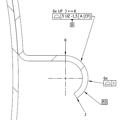
I have been given a drawing and I've not seen datums features called out in this manner and I wonder if anyone has come across these or can advise if this is even correct?! any insight is greatly appreciated, I cant find anything of this on the internet or in any of my books?

Please see the attached images.
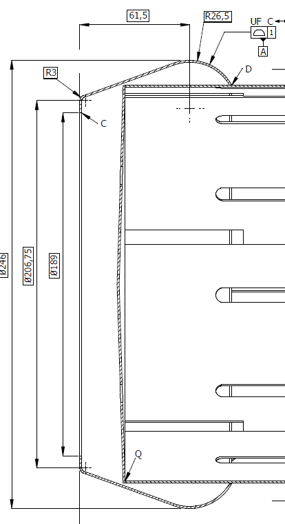
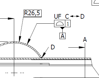
Section through a side wall of a cylinder:
side_wall_of_a_section_through_a_cylinder_vpnh6d.png


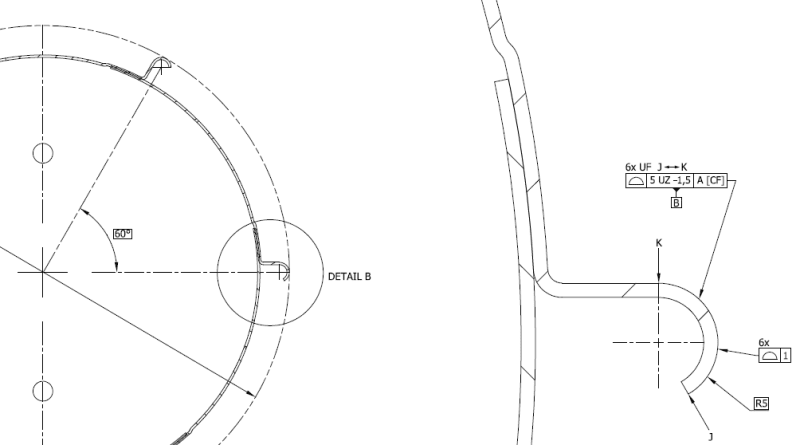
Circular array of these features as viewed from the end of the above cylinder:
Capture1_kfzjpf.png


Many thanks.
 
Replies continue below

Recommended for you

I have limited knowledge in ISO:

UF= united feature
"If the identified features shall be considered as one feature, the UF (united feature) specification element shall be used in conjunction with the “all around” or “all over” symbol."

 
Hi Thanks for the reply but I was more confused with the Datum feature being a surface profile? how does this set up the datum?
 
Again, ISO staff is unknown to a certain extent to me, but I think in ASME would work.
Probably, works in ISO too, but I am not sure.

 
Doug,

I too am not familiar with ISO standards, however if you have a copy of ASME Y14.5-2009 refer to figure 4-29 for an example of a similar surface utilized with a profile tolerance called out as a datum feature. Fig 4-30/4-31 also have similar datum features defined with profile albeit with planar surfaces. The curved surface in question, according to ASME, cannot be called out at as a FOS as it lacks any opposed points. These may give you some idea of how such a datum feature might behave.

I expect this concept translates at least somewhat to ISO, but I don't want to speak in absolutes.
 
Datum Feature Symbol (Datum Indicator as it is know in ISO) can be attached to feature control frame. It indicates that a datum feature is the feature controlled by the geometric tolerance.
In your first image the datum feature A is the area between C and D defined by true profile (Radius 26.5) and it is similar in the second image: the area from J to K (Radius 5 - non-continuous but used as a single feature to create a datum).
The meaning is the same if the datum feature symbol was attached to the feature itself.
You'll find information about the placement of datum feature symbol in ISO 5459:2011; 7.4.2.1 (ASME Y14.5-2009; 3.3.2)
ASME and ISO standards are virtually identical when it comes to datum.
UF symbol belongs to ISO, the closest equivalent, but not the same, in ASME is CF - Continuous Feature. CF identifies a group of 2 or more features of size and treats them as a single feature (interrupted diameters for example)
ISO_5459-datum_indicator_neilpo.gif

ASME_Y14.5-datum_feature_symbol_qgar7d.gif
 
J Macias,

Thats a......comprehensive example of application of datum feature (datum indicator) symbols to a feature vs. FCF. Not sure thats the hangup OP had though - seemed they were more confused about utilizing a feature controlled by profile as a datum feature.

Doug Larkin 17 Apr 19 18:08 said:
I was more confused with the Datum feature being a surface profile? how does this set up the datum?

I directed him to the below example in ASME Y14.5-2009. Perhaps there is an analog in ISO.

fig_4-29_kxynvg.jpg
 
Chez311 - yours is a great example from the standard of how to utilize these features as datum.
ISO 5459, Annex C illustrates association methods for creating datums from datum features.
I thought the confusion was in questioning how can the profile of a surface be a datum feature?
Using certain features to establish datums in practical applications can be very challenging.
Well, I hope at least I clarified Datum symbol placement.
 
As far as I remember ISO 5459:2016 has an example of datum feature A used with profile all around and UF.
Also has some interesting examples of datum established from the flanks of a gear where also UF symbol is used.
So, I would say the practice shown on the OP drawing looks legal, as far as I can see.
But my knowledge and practice in ISO GPS are extremely limited (only few drawings and some standards seen)
 
Hi all,

Thank you so much for the feedback its all very helpful. I'm still having some issues understanding this however and I think i should hae shown a little more of the drawing in image 1. please see below:
Capture2_wwf3pg.png


As you can see the Surface profile datum reference A is defined by a rotated surface profile of the surface C-D. so in my mind this feature c-d will constrain the part to a datum simulator of this surface 1mm larger than the surface form of C-D. So this would sit against the vertical face on the left (ie the plane created by point 'C' with some float on this plane (fitting within the 1mm offset surface profile)

The datum B must be perpendicular to this plane (right?)
This is the end view of the cylinder:
Capture4_lncqto.png

Datum B in my mind would constrain the part with a datum simulator as a 5mm larger surface offset of the radius J-K but this would still allow its centre axis to float and also its rotation to float? Does it? (head starting to hurt!)

...And how I set this up in our software (gom inspect) seems impossible...
 
Presence of a modifying symbol CF (Contacting Feature) in the feature control frame implies that some portions of datum feature are used to simulate datum and contacting features should be specified on the drawing.
ISO 5459:
ISO_5459-CF_aheh2r.gif

In an example below:
“, the datum A with modifier [CF] is a set of two perpendicular planes and not the axis of a cylinder. The first plane contains the datum target points; the second plane is the median plane of the datum target points, perpendicular to the first one. This median plane contains the set of axes of possible associated cylinders (with variable diameters) from the datum target points. If the modifier [CF] had not been used, the datum A would have been the axis of the associated cylinder.”
ISO_5459-CF_figure_mlm9hu.gif

If your drawing contains these targets, use them. This would make measuring a lot easier, actually.
Datum feature A is a complex feature and without CF it must be used in its entirety. I’m pretty sure that datum A shouldn't be simulated with 1mm offset. You’d need to simulate it with “true geometric counterpart” – inverse shape which contacts the surface at its actual location (unrelated actual mating envelope)
To answer a question how datum B should be simulated, you need to look at Datum Reference Frames, which contain datum B and associated modifiers (if present).
 
Status
Not open for further replies.

Part and Inventory Search

Sponsor