Continue to Site

Eng-Tips is the largest engineering community on the Internet

Intelligent Work Forums for Engineering Professionals

  • Congratulations SSS148 on being selected by the Eng-Tips community for having the most helpful posts in the forums last week. Way to Go!

Hilti Profis Alternate 2

Status
Not open for further replies.

Bowsers

Structural
Nov 19, 2019
35
Hello,

I'm doing analysis on an eccentrically loaded bolt group, that is experiencing loads that are both eccentric and out of plane of the faying surface.

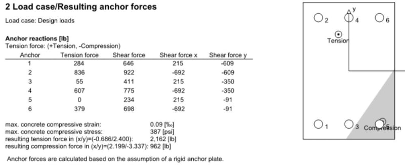
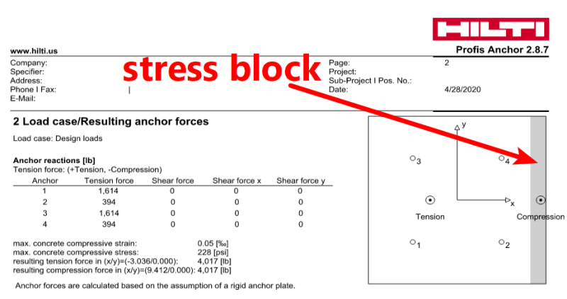
Hilti Profis does this analysis, you can apply Mx, My, and Mz, as well as Fx, Fy, Fz from any point.

I've gone through their design guide (where they validate the software's ability to interpret the loads). If would even use it, except my base-mount material is wood, which has a significantly lower E than concrete.

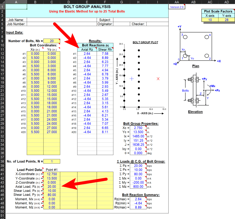
I did manage to find one spreadsheet that does quite a bit of the load generation analysis, but it fails to account for the changing neutral axis location.

Does anyone have a spreadsheet they could share that does this analysis, or an open source hilti alternative that allows for inputting E of wood into the equation?
 
Replies continue below

Recommended for you

If Profis is assuming a rigid baseplate (which I think it does) then the lower E value should not affect the anchor forces.
 

I'm no expert, but it seems like a stretch to be using Profis for an analysis containing a wood base plate.
Have you tried doing it by hand?
 
If elastic and a really rigid baseplate, then think of wood as really weak concrete... results should be the same.


Dik
 
So you have a steel base with wood between the baee and the concrete? Am I interpreting this correctly?
 
Alex T's BOLTGRP.xls will give you the instantaneous center bolt forces for a load at any point in space. Not sure what you mean about the neutral axis changing? Is your wood plate (?) being crushed?
 
Hi All, thanks for the reply so far.

@Retrograde - A lower E value significantly changes the point of bending.

@XR250 - I have validated the shear and tension outputs from hilti for simple load cases. Using their design guide I was able to validate for shear loads in plane with the faying surface are the same between concrete and wood. I also constructed a spreadsheet to validate their eccentric tension loads. The example is attached. I went through and looked at the variables directly relating to concrete (E) and adjusted them to wood to see if the answers remained the same. If so I could use hilti. It was unfortunate that the tension and the location of the neutral axis of the baseplate changed significantly.

@Dik - See above, the results are not the same :(

@XR250 - These are steel baseplate's directly against LSL's and PSL's. They are being lag bolted to the wood. In many of the configurations, it is a bent plate, with the baseplate's connecting to irregular structures.
 
@Dold - The boltgrp excel spreadsheet is what I used for my initial analysis. That analysis takes into account loads that are eccentric to the bolt group. The result is answers that are only in shear.

My loads are both eccentric and out of plane, so their is resulting tension in addition to shear. Hilti (in the detailed report) shows the center of tension, compression, and the individual tension loads of the bolts in the tension zone. It also shows a shear in the X and Y directions, and that is what the boltgroup excel solves for.

I've tried to attach the relevent pages, but it hasn't worked. The section of the manual relating to eccentric tension is the last 5ish pages.

 
@Bowsers,
Seems like you will spend more time with software then you would simply drawing and adding a conservative vector diagram of the bolt demands.
 
Ditto XR250.

BOLTGRP spreadsheet will definitely give you axial and shear reactions in all of the bolts. And you can enter in shear, axial, and applied moments at any point in 3d space.

Maybe a sketch of your situation would help us better understand your problem.

boltgrp_screengrab_uud2oh.png
 
If you know how to locate the neutral axes of the bolt group and calculate moment of inertias, you can write your own spreadsheet by using following formula:

Bolt Tension or Compression T, C = Mx*y/Ix ± My*x/Iy
Bolt Shear V = √[(Fx/n)2+(Fy/n)2+(Tr/Ip)2], n = number of bolts, T = torsion due to eccentricity of forces

 
@Dold Thank you! I must've been looking at another bolt group spreadsheet?! Would you mind sharing a copy of that sheet with me? I'm not part of the excelcalcs family.

@Retrograde -- When you look at a hilti output, a compression zone and tension zone is indicated, with a line dividing the two. That is when the baseplate is acting in compression, and experiances internal stress as it resists the force. This is what I was referring to as the point of bending. Perhaps I misunderstood the concept?

 
Retrograde, I beleieve what OP is talking about (in the profis output) is equivalent to a stress block as we're used to seeing in concrete design. This example has a moment applied about the y-axis. OP, that line between the 'compression' zone and the 'tension' zone is not necessarily where the plate is going to bend. I don't know what youre attaching to the plate, but there are AISC design guides which go through the calculations. I might recommend Simpson anchor designer - it will run FEM analysis on the baseplate. It still seems like you could do this pretty quickly by hand...?

hilti_output_xtffhz.png


OP, here's a link to a treasure trove of spreadsheets. Look for BOLTGRP.xls and download [URL unfurl="true"]https://www.steeltools.org/bolted.php[/url]
 
@Dold - Thanks. Yes, the stress block is what I was referring to. Perhaps not knowing that to call it properly was part of my difficulty in finding the answer I seek.

If you were to run the run the numbers in hilti and in boltgrp sheet the output for tension would not be the same, as a result of the stress block.


Dold's image has some of the bolts carrying compression force, so that's a fundamental difference as you've noted.

For the timber compression, what stress-strain relationship were you planning to use?
 
It seems that BOLTGRP assumes all the forces are transferred through the bolts. It ignores the baseplate bearing.
 
I am a little confused in requiring Young's Modulus and stress-strain relationship for the wood base plate design. Up to this point, the resulting bolt tension and plate compression area are derived from linear force equilibrium, assuming support is rigid (no settlement or material deformation). The follow up will be determine the critical location of the plate, and apply the resulting force/stress against the allowable stresses (ft, fb) of the wood material. Where is E in the process?
 
Answer to my own question - under compressive force, the wood baseplate tends to shorten, or crush. To check this effect, E is required. Here is the link to Young's Modulus for varies wood species. Link
 
Status
Not open for further replies.

Part and Inventory Search

Sponsor