Eng-Tips is the largest engineering community on the Internet

Intelligent Work Forums for Engineering Professionals

  • Congratulations waross on being selected by the Tek-Tips community for having the most helpful posts in the forums last week. Way to Go!

Hip Roof with No Ceiling...Thrust???

Status
Not open for further replies.

youngblood30

Structural
Jan 28, 2020
14
0
1
US
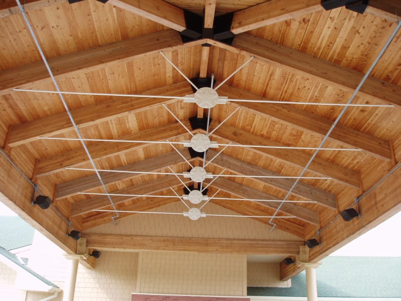
I have a little 16x28 partially enclosed outdoor pavilion. It has a typical hip roof with no ceiling framing(cathedral style). Really scratching my head on the best way to deal with thrust here. I have a full wall on one side (shorter side) and short little corner walls on the other short side. The longer sides have posts and beams supporting the rafters. Is it best to design the hips to transfer thrust to the corners?

The other kicker here is the Architect calls for no exposed fasteners either.
 
Replies continue below

Recommended for you

Is it just rafters, or is it a scissor truss? A scissor truss will be self restraining - it'll deflect outward, but because there is effectively a "moment connection" at the peak, it'll eventually stop. Then you just have to be sure the walls/beams can survive the little bit of lateral deflection. If you just have a ridge board with rafters, you have a problem unless you fix the base of your wall somehow (no small task in wood construction). Another option could be going to a ridge beam spanning the length of the building. Hard to do with a hip, but maybe you could get the architect to allow a decorative truss at each end?
 
I assume that this is pitched stick framing of some sort. If so, search hard here for past threads on this topic. I know that this has been discussed in great detail a few times in the past.

1) using the top plates or a structural fascia as a tension ring is a popular choice. The connections are critical.

2) another path that I've seen taken is to make a moment connection between the hip rafters and ridge beam.

Some issues that warrant at least cursory consideration:

2) uplift resolution.

3) difficult connections delivering the thrust to the ring beam, whatever that is.

4) overall stability of the skeletal framing under unbalanced loads, depending on the diaphragm capability of your sheathing.
 
I think you'll need to have beams on all 4 sides that carry the thrust, akin to a tension ring, except that the beams will also be working in weak axis bending toward mid-span. I expect that you'd need to add something to add capacity to the beams in the horizontal axis.

Also consider adding horizontal steel rods that tie the long side beams together.
 
It is all rafters no scissor trusses...throw in a small cupola up top so the ridge board isn't even continuous to each side of the hip intersections. The only beneficial thing I see is that its only 16' wide....at first glance the only solution I see(without going back to the architect) is to design the beams to take the thrust and transfer to columns with a moment connection at the base.
 
The cupola kinda screws your thrust arrangement. Maybe you moment connect your short span rafters across the ridge and effectively make your own scissors/parallel chord truss.
 
Or, design the cupola opening as a compression ring and the top plates/beams as a tension ring. That would be pretty neat if you could pull it off.
 
You could also use horizontal tension rods across the "ceiling" plane.
This concept:
P5290042_ck6gzw.jpg
 
I typically use the tension ring concept for square situations such as this.

For your situation though, I would add tension rods to the tension ring - maybe two or three as needed, considering the top plate or edge beam to be able to span between the tension rods.

Mike McCann, PE, SE (WA, HI)


It always amazes me that these discussions don't get into the bending moment in the sheathing plane is not mentioned. For a model of that situation fold a cardboard into the shape of the roof and load it up.
 
You are correct, and there have been discussions on that issue in the past here.

Bending moment or not, you still have the horizontal spreading to control. I just ignore the existing diaphragm action in bending and use it as redundancy.

I employ the KISS principle...

Mike McCann, PE, SE (WA, HI)


OG - I think the other issue there is that most of our wood diaphragm design data is based on particular testing setups. I don't know that it's really valid for assessing shears caused by a resistance to spreading of the roof while also resisting in plane shears from horizontal loads. I agree from first principles it should be straightforward, but wood diaphragms are largely driven by empirical data and equations. If somebody else knows better, please correct me.
 
I have seen tons of houses with structural-less vaulted hip or gable roofs performing just fine. I have seen just as many with wall spreading issues.
Perhaps it comes down to size and how well the sheathing was nailed.
I never count on the diaphragm in my analysis.
FWIW, I was the engineer for that FHB article (The contractor is a customer of mine).
 
XR250,

What do you see as feasible spans in your experience with this type of beams?
I did some quick rough calcs and it seems that it becomes equivalent lightish W8 .... with "average" loadings up to 20 feet spans seems sane?
 
Not sure what is sane (or if I am even sane). I have done one with a W10x77 in a really big garage.
Usually, I switch to I-beams after about 16 ft.
 
Status
Not open for further replies.
Back
Top