Continue to Site

Eng-Tips is the largest engineering community on the Internet

Intelligent Work Forums for Engineering Professionals

  • Congratulations SSS148 on being selected by the Eng-Tips community for having the most helpful posts in the forums last week. Way to Go!

Hip Roof

Status
Not open for further replies.

Tinguindin

Structural
Oct 15, 2008
24
Hello Guys;

I am currently working on a patio cover, please see the attached sketch. The architect wants me to remove two interior beams where the king posts are landing. I have seen several hip roofs without interior supports, but I just don't get how they are working. It seems that the diaphragm is somehow holding the roof together, but how do I calc this out.
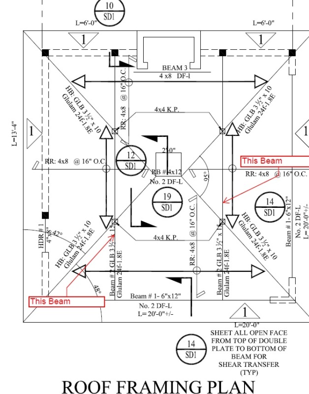

Sketch_evocdc.jpg


Any ideas, I will appreciate them.

Thank you.
 
Replies continue below

Recommended for you

Trusses? That is how most hipped roofs are framed these days.
 
So I assume you want this vaulted? If so, The way I usually do it is designing a "bent" I-beam or Flitch beam (in thew 20 ft. direction) to support the roof. It is expensive and a pain in the ass for the contractor but has so far worked well.
 
Or the four perimeter beams serve as a sort of tension tie for the four diagonal ridge beams. However, in your case you have a short ridge at the top which introduces some complexity.
I think it can possibly still work but you'd have to think it through.


Check out Eng-Tips Forum's Policies here:
faq731-376
 
We had a quite comprehensive thread on this a few months back where we established that this could be done without the heLp of the diaphragm for systems where all of the ridge beams meet at a point. I'd push your architect to adjust the slopes such that the rafters do meet at a point. Without either relying on the diaphragm In a complex manner or creating a rafter to rafter moment connection, I believe that the length of flat ridge line at the top renders the system unstable.

I like to debate structural engineering theory -- a lot. If I challenge you on something, know that I'm doing so because I respect your opinion enough to either change it or adopt it.
 
I agree with Koot. All four hips must meet at a point for this to be stable without the two beams to be eliminated.

Mike McCann, PE, SE (WA)


OP said:
What about the connection at this point where the 4 hip beams meet and also at the walls?.

You need a ring beam capable of transmitting axial tension and compression across the corner joint and up into the rafters. That ring beam could potentially be just your top plates if detailed correctly. I guess it's less a ring beam than a ring tension tie.

I like to debate structural engineering theory -- a lot. If I challenge you on something, know that I'm doing so because I respect your opinion enough to either change it or adopt it.
 
The hip to plate detail can be tricky to design and construct to resist the thrust. That is why I typically go with the bent beam approach.
It will also let you keep you ridge. Although, I doubt a short ridge like that would make Kootk's idea unstable.
 
With the short ridge beam, you will need moment connections to the ridge at the hip connections. You will not without it. The connections at the walls will direct the lateral kick to the ring beam, or to the corner shear walls if you want to drop the ring beam, which I do not advise.

Without the ridge beam, it is just a two way arch with a pin at the ridge.

Mike McCann, PE, SE (WA)


I disagree. The hips are in compression and just push against each other with equal force into the ring beam corners. The short ridge will simply act as a compression member between them. Sure, if you model it in a 3D program with pinned joints, it will be unstable. In reality, the depth of the ridge and the fact that it is nailed well to the hips will keep it stable. A longer ridge may be another story.
 
As well as the structural issues, you should consider the geometry. This thing looks square in plan, an if so, there will be two different slopes meeting at the hips. Ever try framing that? 45 degree hips work best.
 
I would have to think about that, particularly with any unbalanced loading causing torsion. The roof diaphragm would have to come into play here too.

Mike McCann, PE, SE (WA)


The stability issue revolves around the potential for one of the peaks to shift upwards while the other shifts downwards. And, without doubt, that is what would happen with truly pinned connections in the absence of sheathing and secondary framing. Even with symmetrical loading, that would only produce a condition of neutral stability. And, in our sphere, neutrally stable = unstable.

I like to debate structural engineering theory -- a lot. If I challenge you on something, know that I'm doing so because I respect your opinion enough to either change it or adopt it.
 
4 hinged arch might be another analogy... one too many. all the framing cuts are trickier too with the two different slopes introduced by the 2' ridge beam and the 95 degree plan view angle shown as hokie66 points out.

if ridge eliminated, i'd design as others said above and for constructability i'd look at a peak connection made with something like 1/4" or 3/8" custom fabricated steel bucket and bolt system connecting two diagonally opposite hips together as a stable standalone system first and then 'hanging' from that the other two hips also supported by buckets shop welded to the others, ie all one fabricated piece. i'd probably specify tight fit everywhere to take the compression but design the bolts to take all the compression too. you could add a square non structural fill plate from the underside where the 4 buckets converge to get a nice symmetrical look from below.

if i'm see it right, the tension ring at the bottom seems complicated by the design with the rafter over the tension ring beams...the lateral component of your hip thrust is above the centroid of the tension ring members introducing a vertical plane moment at this condition. perhaps a deeper hip beam combined with a shallower rafter can get the eccentricity to a palatable point, or perhaps you introduce a shallow steel member, so not too obvious, affixed on top of the perimeter beams and aligned with the centroid of your hips to act as the true tension tie.
 
Interesting question would be:

If with unbalanced snow loading the tension in the tension ring would be the same all around or not?

Mike McCann, PE, SE (WA)


It would have to be. It is essentially a cable.
 
You would think so, but then how would you reason the different thrust reactions from each of the hips due to the differential loading? It's almost like the tension link would have to equal out all the compression loads on the hips, but each hip still seeing it's own bending stress.

Mike McCann, PE, SE (WA)


I'll surely regret committing to this In print but, on an asymmetrically loaded symmetric system, I think that the axial forces end up being the same in all rafters. The would be thrust differeential flows into the ring beam, back up the opposing rafters, and balances out the thrust in the originating rafters. I believe that is what crests the very important demand for axial load transfer between rafters at the peak.

I like to debate structural engineering theory -- a lot. If I challenge you on something, know that I'm doing so because I respect your opinion enough to either change it or adopt it.
 
I'm supposing that the tension in the ring would be constant all around, such that the horizontal component of each hip reaction is the same but the vertical component of each hip reaction varies based upon it's own loading condition...such that an asymmetric load on the pyramid, an unbalanced snow load or construction load, a load on one face of the pyramid can induce a bending moment in the opposing unloaded face of the pyramid.
 
Status
Not open for further replies.

Part and Inventory Search

Sponsor