Continue to Site

Eng-Tips is the largest engineering community on the Internet

Intelligent Work Forums for Engineering Professionals

  • Congratulations SSS148 on being selected by the Eng-Tips community for having the most helpful posts in the forums last week. Way to Go!

Hip Roof

Status
Not open for further replies.

Tinguindin

Structural
Oct 15, 2008
24
Hello Guys;

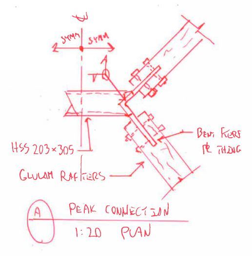
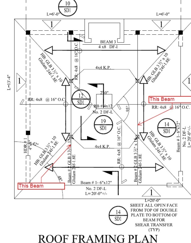
I am currently working on a patio cover, please see the attached sketch. The architect wants me to remove two interior beams where the king posts are landing. I have seen several hip roofs without interior supports, but I just don't get how they are working. It seems that the diaphragm is somehow holding the roof together, but how do I calc this out.


Sketch_evocdc.jpg


Any ideas, I will appreciate them.

Thank you.
 
Replies continue below

Recommended for you

Based on statics and geometry, how can the vertical components vary and the horizontal remain the same? The resultant force in each hip must follow the slope of the hip member.

Mike McCann, PE, SE (WA)


My proposition is that the axial loads in the rafters would be the same and the transvers loads would vary based on loading.

Considering how short the ridge is and the need to make a moment connection of it, perhaps that entire 2' chunk should just be steel.

I like to debate structural engineering theory -- a lot. If I challenge you on something, know that I'm doing so because I respect your opinion enough to either change it or adopt it.
 
How would you make a steel to wood moment connection? The only decent wood moment connections I've ever seen used steel straps at the top and bottom.

Also, has anyone had much success with wood moment connections period? Most studies I've read and connections I've seen in person have a problem with excessive rotation before any moment is transferred.
 
could be visualizing incorrectly, wouldn't be the first time, or the second, or well nevermind .... but as a 3 member planar truss with a point load at the apex has equal horizontal reactions and equal vertical reactions with resultants aligning with the slopes indicating pure axial loads in the members, wouldn't an asymmetrically placed point load result in equal horizontal reactions with unequal vertical reactions and resultants unaligned with slopes, the unaligned resultant being resolved in design by the moment capacity of the member?
 
Jerehmy said:
How would you make a steel to wood moment connection?

I was thinking of something like the detail below. As XR250 alluded at the top, the demand here would be nominal. Additionally, as you pointed out, the issue with wood moment connections tends to be deformation. And this particular connection wouldn't be too sensitive to that. I wouldn't do this for a serious moment connection.

Jerehmy said:
Also, has anyone had much success with wood moment connections period? Most studies I've read and connections I've seen in person have a problem with excessive rotation before any moment is transferred.

In general, I agree with these sentiments. My wife's firm actually runs a brisk trade doing side work as timber connection specialists in delegated design situations. They've had a good deal of success with wood to wood moment connections using things like timber rivets and the sexy hardware -- and associated design methods -- coming out of Europe.

Capture_as3plv.jpg


I like to debate structural engineering theory -- a lot. If I challenge you on something, know that I'm doing so because I respect your opinion enough to either change it or adopt it.
 
What do they do to combat the shrinkage issue of connecting the rigid steel plate to the wood, unless there's only 2 bolts or the bolts are spaced less than 5" vertically. I'm just curious. Also, do they test these assemblies? Thinking of checking analyzing a multi-bolt wood moment connection seems like a headache.
 
If the ridge is short, the rafters/diaphragm will keep it stable. For it to rock up and down, one pair of rafters would have to move up and the other nearby rafters would have to move down. Which means their heel ends would have to move in and out. The diaphragm will prevent this.
 
@Jerehmy: I don't know how the address shrinkage. I just spectate and admire. I can tell you that it's a rather lucrative endeavour. I design whole buildings for less than they charge to euro-connect a few dozen shiny glulam portal frames.

@XR250: I see it and I agree. My faith in it would be, in part, a function of roof pitch. What I'd agree with at 12:12, I might object to at 3:12. For stability stuff, I just prefer a load path that's a little more... discrete. I'll stamp yours if you'll stamp mine.

I like to debate structural engineering theory -- a lot. If I challenge you on something, know that I'm doing so because I respect your opinion enough to either change it or adopt it.
 
curious and getting some time, I ran some numbers for a roof as above, except all hips meeting at a point, under snow load conditions. I treated diagonally opposed hips, together, as a 3 hinged arch. For snow on all 4 quadrants, or 3 or 2 or 1 quadrant, I found tension constant on 4 sides although hip vertical reactions vary. pleasantly ...pleased.
 
20 ft and almost square doesn't seem like too much weight/thrust resistance needed.
The short ridge does make it unstable in IMO. Something like a steel flitch there that runs down the opposing hips might be viable to give reliable stability. Then, good connection at the 4 corners and tension in the top plate of the wall should do it.

I have used the "bent" steel frame many times and like that idea too. Might be able to use two of them here, one at each end of the ridgeline (or the peaks of the hips).
 
yea I like that too. In the (OP) ridged scheme, I'm concerned mainly about the horizontal moment between the opposing hips....haven't fully worked that out as yet.
 
Status
Not open for further replies.

Part and Inventory Search

Sponsor