Continue to Site

Eng-Tips is the largest engineering community on the Internet

Intelligent Work Forums for Engineering Professionals

  • Congratulations SDETERS on being selected by the Eng-Tips community for having the most helpful posts in the forums last week. Way to Go!

Hole location

Status
Not open for further replies.

gabimo

Mechanical
May 2, 2013
124
Hole_s6h76k.png


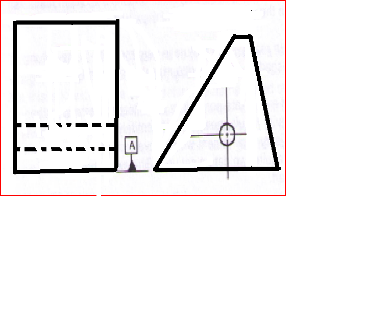
Hole is used as a secondary datum feature (B) in the assembly:

I was told that using position to control only the orientation of the hole is a nay-nay in ASME 2009.
The the question becomes how to control its location?
A-primary= a flat surface
B=secondary datum feature. Should be only oriented to the primary, correct?
Then what about its location to A?

Should be a basic dimension shown from A?
 
Replies continue below

Recommended for you

Since the hole is at a distance from A, you can (common wisdom) use position with a basic dimension. The faces of the part can then be located and oriented to the two datums.
 
All,

Again, per my (and others around the company I am with) understanding is, since datum feature B is secondary, it needs only an orientation control to the primary (surface A).
So, someone idea was to control only its parallelism to datum feature A. And to control all the other features / surfaces --including the sides --- with profile to A primary and B secondary. (with basic angle to the horizontal datum feature A).

But the issue was (and still is) how far from A datum feature B needs to be?
Is it appropriate to have a ± dimension from A (along with its parallelism)?

Do you have any good examples of this case shown somewhere? (including some GD&T books)?
 
It's a set of rules. There is no need for examples of every possible rules-compliant solution.

Datum B needs to be 5 mm from A.
 
gabimot said:
Again, per my (and others around the company I am with) understanding is, since datum feature B is secondary, it needs only an orientation control to the primary (surface A).

Though many examples show that strategy, there's nothing forcing you to do that.

If you want published examples of a secondary datum feature being located relative to a primary datum feature with basic dims, see Figures 4-29 through 4-32 in the 2009 standard. However, as 3DDave says, a lack of a specific example in the published literature is not proof of much.
 
gabimot,

Datum[ ]A is the bottom face of your part. If datum[ ]A were the front face, a positional tolerance on the hole would control perpendicularity. As it is, a positional tolerance on the hole controls elevation and parallelism.

--
JHG
 
Nescius said:
If you want published examples of a secondary datum feature being located relative to a primary datum feature with basic dims

I guess I would like some examples of a secondary datum feature being ORIENTED relative to a primary datum feature (not located).
4-29 - 4.32 shows B= secondary datum feature being the surface (or the middle plane) as a secondary and in my case the surface is primary (not secondary).

Therefore, the question still remains: how to ORIENT (not locate) the secondary datum feature (the thru hole) to the primary one (the bottom surface)?
Why I want to orient only (the hole) and not locate it? Because it is secondary datum feature and then only needs ORIENTATION (not location).
Then I will locate everything else to it or to the DRF made from A primary and B secondary.


drawoh said:
If datum A were the front face, a positional tolerance on the hole would control perpendicularity

Well, it is not , hence my dilema/ question.....

drawoh said:
As it is, a positional tolerance on the hole controls elevation and parallelism.
yes, but the positional callout/ tolerance will LOCATE the hole and I don't want that the hole to be located. I want it to be only ORIENTED to the primary datum feature A (the bottom surface)


gabimot,

It sounds to me as if your hole should be the primary datum, and the bottom face the secondary datum. On the bottom face, you specify parallel, profile, and possibly flatness.

--
JHG
 
drawoh said:
It sounds to me as if your hole should be the primary datum, and the bottom face the secondary datum. On the bottom face, you specify parallel, profile, and possibly flatness.


The physical reality of this assembly is that the part is sitting on datum feature A and then the hole is used with its mating component (not vice-versa). The hole is free to float - up and down within some tolerance from datum feature A.

 
gabimot,

How about you place a composite FCF showing an accurate parallel tolerance, and a sloppy positional tolerance?

--
JHG
 
drawoh said:
How about you place a composite FCF showing an accurate parallel tolerance, and a sloppy positional tolerance?

Could you please provide more details? Thank you.
Can I locate the hole in only one direction (only vertical) and the position callout is still valid?


gabimot,

If your positional tolerance is from datam[ ]A, it can only work from one direction, up and down.

--
JHG
 
So, will be a composite with no diametral symbol "Ø" vertical aligned?
What about the lower segment? Will it have "Ø" symbol ?

 
If the shape of the hole's tolerance zone is a cylinder then you need the dia. symbol.
 
But the issue is that is controlling the position in only one direction?
 
If the hole is the primary datum feature then you can profile the surfaces w.r.t. the hole.

Yes, functionally the bottom surface is the primary datum but sometimes compromises can be made (if there is a good enough reason - I have had to do this before). How much of a difference is there (tolerance-wise) if the bottom surface is profiled from the hole instead of if the hole is positioned from the surface? If there is a difference can you adjust the tolerances of these feature to compensate?
 
gabimot:

It appears you might need to re-familiarize yourself with the control of motion offered by position vs orientation. There are 3 translation and 3 rotation degrees-of-freedom (DOF) of motion - see 4.4 Orientation only restricts rotational DOF - see para 6.4. Position can control all 6 DOF depending on the number of datums specified.

Certified Sr. GD&T Professional
 
mkcski,

Gabimot's problem is that his hole is datum[ ]B[ ](C???). The part is not yet restrained when the hole is measured. At some point, the front or rear face must be selected as a datum. The measurable tolerance zone for the hole is a straight line up and down. He could just as easily apply a [±]tolerance to the hole, although I understand this is being disparaged by the standard.

--
JHG
 
Neither the front or rear face is required to be a datum. The bottom face and the hole are sufficient to fix the location and orientation of the part.
 
gabimot,

The drawing should have a basic dimension between datum feature A and the hole axis. This is required to properly construct the datum reference frame you describe based on the two features. Refer to ASME Y14.5-2009 para. 4.5.2 for the specific requirement.

To control the distance between datum A and the hole axis, an ordinary RFS position tolerance with a cylindrical tolerance zone is perfectly appropriate. Why do you feel this is a problem?

If you want to control the orientation of the hole axis relative to datum A to a tighter limit than the position, you could additionally apply a parallelism or angularity tolerance. Again, a cylindrical tolerance zone is fine.


pylfrm
 
Status
Not open for further replies.

Part and Inventory Search

Sponsor