Continue to Site

Eng-Tips is the largest engineering community on the Internet

Intelligent Work Forums for Engineering Professionals

  • Congratulations SDETERS on being selected by the Eng-Tips community for having the most helpful posts in the forums last week. Way to Go!

Hole location

Status
Not open for further replies.

gabimo

Mechanical
May 2, 2013
124
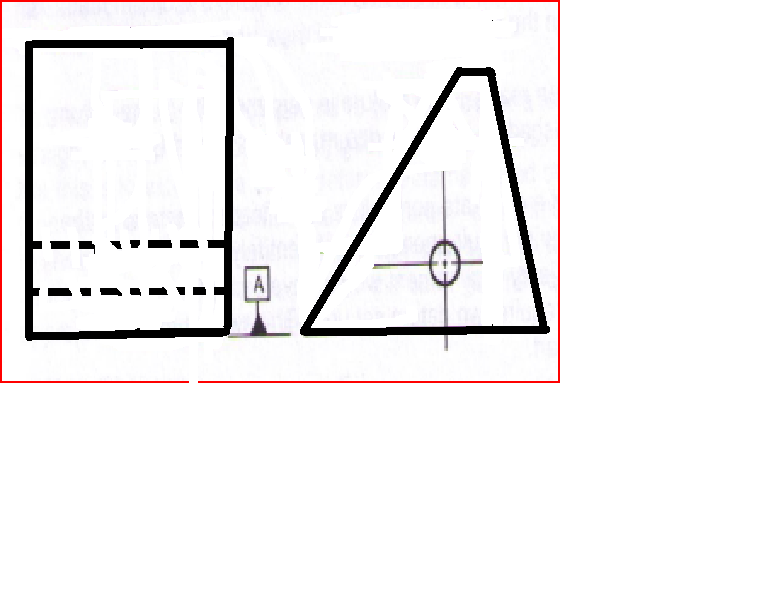
Hole_s6h76k.png


Hole is used as a secondary datum feature (B) in the assembly:

I was told that using position to control only the orientation of the hole is a nay-nay in ASME 2009.
The the question becomes how to control its location?
A-primary= a flat surface
B=secondary datum feature. Should be only oriented to the primary, correct?
Then what about its location to A?

Should be a basic dimension shown from A?
 
Replies continue below

Recommended for you

pylfrm said:
To control the distance between datum A and the hole axis, an ordinary RFS position tolerance with a cylindrical tolerance zone is perfectly appropriate. Why do you feel this is a problem?

Because we want to control only the hole's orientaion to datum feature A (the flat surface) and not its location. Everything else is controlled FROM A primary and B secondary.

The idea is that the secondary datum feature should be oriented to the primary. (if there were two holes then position is the correct way to call it since position will also control the mutual relationship between the holes, but in my case there is only one hole hence the conundrum)

Maybe the idea and the concept that the secondary datum feature must only be oriented to the primary is not always applicable. So, I am looking for some examples (GD&T books/ pages or websites) where I can see other good applications of the method.

 
3DDave,

The bottom face locates in elevation, and two rotation axes. Based on the OPs commments, the hole stops side to side movement, and the other rotation axis if it is datum[ ]B. What keeps it from moving fore and aft?

--
JHG
 
Nothing. It isn't required if it's just the prismatic shape shown.

Make the front and back faces profile to [A|B] and viola.
 
I haven't read every response in this thread so forgive me if this has already been stated. The control of the secondary datum feature is determined by its relationship to the primary. If the only relationship the secondary has to the primary is orientation, then all you need is an orientation tolerance. If the relationship is one of location then you need a locational tolerance. In this case the relationship is locational since the hole is a certain distance from A. Yes, the hole is parallel to A but location trumps orientation when it comes to datum referencing. If the hole was actually perpendicular to A then there is no more locational relationship and only orientation remains, thus you could legally use just perpendicularity as the datum feature control.

John Acosta, GDTP Senior Level
Manufacturing Engineering Tech
 
I remember a thread not too long ago where the question of using position to orient the secondary datum feature (of size) was discussed. The secondary datum feature was perpendicular to the primary datum feature (surface). This was discussed at length and pretty much everyone agreed that orientation should be used for a single feature and position can be used if multiple features (of size) made up the secondary datum feature. We never discussed what to do if the secondary datum feature (of size) was parallel to the primary datum feature. I think this is what was tripping people up (myself included). I think that some of us were assuming that the perpendicular case carried over to the parallel case.
 
gabimot said:
Should be only oriented to the primary, correct?

It does not actually matter if the hole is datum feature or if it is just an ordinary hole controlled relative to some datums. It simply needs a location tolerance to avoid incomplete drawing specification. With parallelism only, the hole can wander up and down without any limitation, which is a serious drawing error.


3DDave said:
Nothing. It isn't required if it's just the prismatic shape shown.

Make the front and back faces profile to [A|B] and viola.

True, but you can also just use A on the drawing and control the hole with position to A and the outline with profile to A. B will not be needed then at all.
 
Status
Not open for further replies.

Part and Inventory Search

Sponsor