Continue to Site

Eng-Tips is the largest engineering community on the Internet

Intelligent Work Forums for Engineering Professionals

  • Congratulations KootK on being selected by the Eng-Tips community for having the most helpful posts in the forums last week. Way to Go!

Hole Pattern as Datum with different hole depths

Status
Not open for further replies.

G_Apache

Mechanical
Jul 7, 2022
6
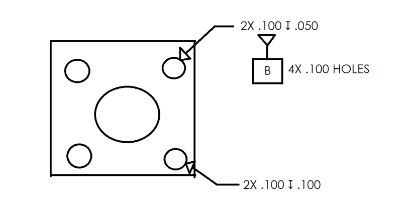
Our set up is nearly identical to ASME Y14.5-2018 Figure 7-18.
I want to convey that the 4-hole hole pattern is to be considered the datum. However, the hole callouts are split into 2, with 2X holes having a different depth than the other 2X.
I am getting pushback that the way I annotated the datum feature symbol is confusing.
How would you represent that it is not the 2X hole pattern that makes up datum B, but all 4 similarly sized holes?
See the image below - unnecessary details have been omitted.
Hole_Pattern_eglfee.png
 
Replies continue below

Recommended for you

If the setup is very similar to fig. 7-18, apply position tolerance relative to A to the first pair of holes, then add datum feature symbol B to the position FCF. Do the same thing with the second pair of holes, except use C as the datum feature letter.

Then use |A|B(M-C(M)| where needed.
 
Use a separate datum symbol callout with 4 leaders.
Use a separate datum symbol callout with one leader and the "4X 0.100 HOLES" separately from the hole callout.
Call out each hole pair as a separate datum feature and use, for example, B-C or B(M)-C(M), as a datum feature reference.
Make a note that holes with a letter indicator form a single datum feature and mark the holes that participate.
 
Alternatively, you could specify it exactly as in figure 7-18 and handle the depths separately; Instead of specifying the depths after the diameter callouts, show the depths in 2 separate section views.
 
pmarc,

Do you agree with Burunduk's approach? Breaking the depth from the location control make sense to me specially looking in fig 10-52/2018 (where the standard broke size requirements from the location control due to the different sizes for the applicable holes).

So, I assume the same concept could be applied here, so separate the depth from the location make sense to my untrained eye (in the Y14.5-2018)

I am wondering what is your opinion?

 
greenimi,
I see nothing wrong with Burunduk's proposal.
 
Burunduk's proposal is perfect as long as the diameters and diameter tolerances are identical for all the holes in the pattern. It does add the requirement for section views to show the depth and the option that those depths, disconnected from the diameters, will be misread, but it would work perfectly.
 
My opinion would be not to use the 4 hole pattern as a datum. Use the back surface then two of the edges, or the back surface, one edge, and the center hole. Whichever is more applicable to how the part will be assembled and function. Using a pattern of holes for a datum seems like a pain to qualify.
 
Status
Not open for further replies.

Part and Inventory Search

Sponsor